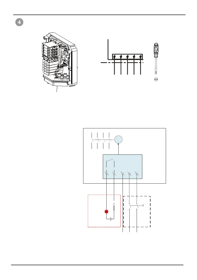
Wire the power AC connection to the terminals.
Note: FB1, FB2 are used to remotely display the on and off states of the switch.
When the switch is closed, FB1 is connected to FB2; when the switch is open,
FB1 is disconnected from FB2.
The enclosure needs to add a M12 cable gland if the remote display function is
needed.
5
FB1
(option)
(AC Cable: MAX. 0.75 mm²)
CN4
FB2 PE N L
FB1
FB2
PE
N
L
M
MCU-CONTROL
DR
External power
Indicator light
AC distribution box
PEFS
Monitoring room
Note:
External power: +5~48V,>150mA
Resistance: metal shell,>10W
Resistor is selected according to supply voltage, to ensure circuit current less
than the rated current of the Indicator light and <320mA
Resistance
FB1 FB2 PE N L
AC Current: 30mA
Operating voltage: 100Vac - 270Vac