3
Model Nominal Battery DC Voltage
Pro1200VA 12
VDC
Pro2400VA 24
VDC
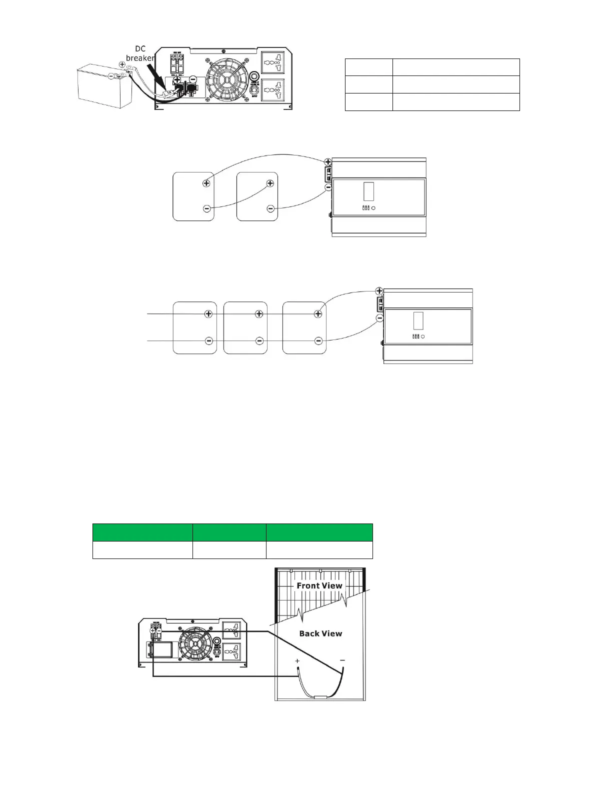
Fig. 2
Table 1
2) Multiple batteries in series connection(Refer to Fig. 3): All batteries must be equal in voltage and
amp hour capacity. The sum of their voltages must be equal to the nominal DC Voltage of the unit.
Fig
3
3) Multiple batteries in parallel connection(Refer to Fig. 4): Each battery's voltage must be equal to the Nominal
DC Voltage of the unit.
Fig
4
Step 6- Make sure to connect the polarity of battery side and the unit correctly.
Positive pole (Red) of battery to the positive terminal (+) of the unit.
Negative pole (Black) of battery to the negative terminal (-) of the unit.
Step 7- Put the covers back to the external battery terminals.
Step 8- Take the DC breaker on.
Connect to Solar Panel
CAUTION: Before connecting to PV modules, please install separately a DC circuit breaker between inverter
and PV modules.
WARNING! All wiring must be performed by a qualified personnel.
WARNING! It's very important for system safety and efficient operation to use appropriate cable for PV module
connection. To reduce risk of injury, please use the proper recommended cable size as below.
Typical Amperage Gauge Torque Value
50A
8 AWG 1.4~1.6 Nm
Step 1- Connect one cable to the positive (+) pole of solar panel and solar charger positive (+) terminal.
Step 2- Connect the other cable to the negative (-) pole of solar panel and solar charger negative (-) terminal.
Solar Panel
Connection