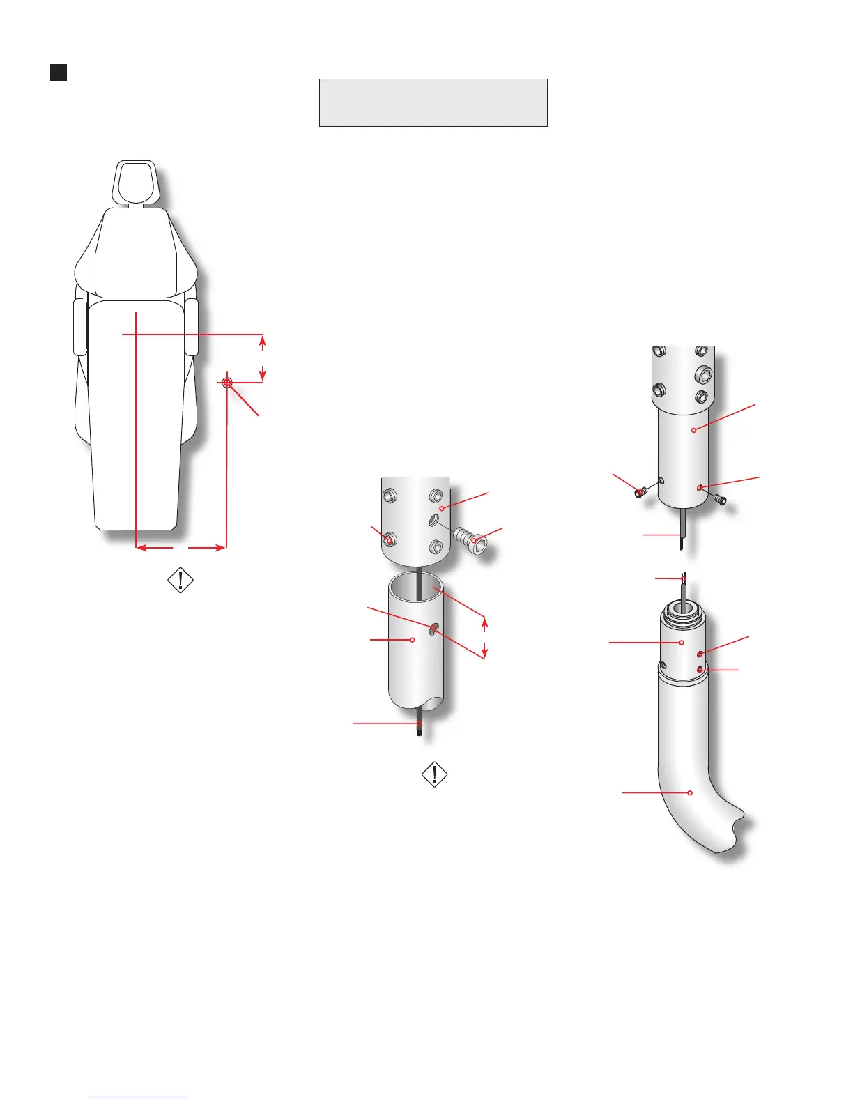
12”
18”
Drop Post
Support Hub
5/16” Bolt
5/16” - 18
Set Screw
Drop Post
Pigtail
11/32”
Diameter
1 5/8”
Figure 2
10-32 x 1/4”
Button Head
Drop Post
Clearance
Holes (3)
Pigtail - Low
Voltage Cable
Spade Terminals
Swivel
Rigid Arm
Figure 3
Rotation
Stop Screw
Tapped Holes
(3)
3
Figure 1
Installation Notes
1.
2.
3.
4.
5.
6.
7.
Follow recommended dimensions
on Figure 1 to determine the position
for the support plate.
HAZARD
Check ceiling structure and deter-
mine that it will support a minimum
of 200 pounds. Failure to fasten ceil-
ing securely to a structurally sound
and appropriately designed structure
could result in a hazard of potential
injury to patient or users caused by
the light falling.
Note: It is the responsibility of a
licensed mechanical structural engi-
neer to verify that each site is safe to
mount such device.
Using drill template provided on
page 6, mark mounting hole centers.
Mount the support plate to ceiling
using three (3) 3/8” diameter lag
screws.
Note: The ceiling light is designed to
accommodate up to 11’ ceiling. The
drop post is pre-cut to suit your ceil-
ing height.
Ceiling Height 8’ 9’ 10’ 11’
Drop Post Length 9” 21” 33” 45”
Proma discourages the use of
ceiling exceeding 11 foot heights.
Proma suggests the use of a cabinet
mounted or wall mounted light.
Note: The drop post has an 11/32”
(.343) diameter hole on the center-
line, 1-5/8” inches from one end.
This is a clearance hole for the 5/16”
bolt that secures the post to the sup-
port hub.
Route the pigtail from the transform-
er through the drop post containing
the 11/32” diameter hole. Next, insert
the post into the support hub.
Note: Align the hole on the drop post
with the 5/16” socket cap bolt. Tight-
en the 5/16” bolt and let the drop
post rest on the bolt. See Figure 2
HAZARD
Failure to install the 5/16” bolt as de-
scribed may allow the light to fall and
could result in personal injuries.
Tighten the eight (8) 5/16” – 18 set
screws on support hub. Assure that
post is level front to back and side
to side.
Slide the ceiling cover and collar
onto the drop post. Once cover is
on post and resting on the ceiling,
tighten two (2) set screws on collar.
Connect the terminals from the rigid
arm to the pigtail terminals from the
low voltage cable being careful to
match the colors.
Insert the swivel (part of the rigid
arm) into the drop post. With the
rotation stop set screw, located in
the swivel, towards the foot of the
chair, align the three (3) holes on the
drop post with three tapped holes on
the swivel and secure with the three
(3) 10-32 x 1/4” button head screws
provided. See Figure 3.
Test Light
Turn the light switch located immedi-
ately behind the light head. This is a
three position switch. Center is Off,
Left is the normal operating intensity
and Right is maximum intensity for
color matching.
8.
 Loading...