2/5
QBT Installation Guide - 3/22/2016 | SSS
RE-CALIBRATION PROCEDURE
All QB control valves come calibrated from the factory by trained
personnel using precision calibration equipment. The QB valve is a
closed loop control valve using a precision electronic pressure
sensor. Typical drift is less than 1% over the life of the product. If
your QB valve appears to be out of calibration by more than 1%, it is
not likely to be QB. Check the system for plumbing leakage, wiring
and electronic signal levels. Verify the accuracy of your measuring
equipment before re-calibrating. Consult factory if you have any
questions or require assistance. If the QB valve needs re-
calibration, use the procedure described below:
QB1 VALVES
1. Identify the inputs and outputs of the valve using the model
number of the valve, calibration card included with the valve, and
the information provided in this sheet.
2. Connect a precision measuring gage or pressure transducer to
the OUT port of the QB.
NOTE: THERE MUST BE A CLOSED VOLUME OF AT LEAST
1 CU. IN. (17 CC) BETWEEN THE VALVE OUTLET AND THE
MEASURING DEVICE FOR THE VALVE TO BE STABLE.
3. Connect the correct supply source to the IN port of the QB,
making sure the pressure does not exceed the rating for the
valve (See Table 1).
4. Locate the plastic calibration access cap on top of the QB valve
and completely remove it. Located underneath are two
adjustment trim pots, Zero “Z” and Span “S”. See figure 1 for
pots location.
5. NOTE: Only use this step if your device is totally out of
calibration. If it is slightly out of calibration, omit this step and
move on to paragraph 6. Using a small screwdriver, turn both
trim pots 15 turns clockwise. Then turn both trim pots 7 turns
counterclockwise. This will put the QB roughly at mid-scale.
6. Make correct electrical connections as noted. Make sure there is
a proper meter in place to measure the command input to the
QB.
7. Set the electrical command input to MAXIMUM value.
8. Adjust the SPAN pot until MAXIMUM desired pressure is reached
(clockwise increases pressure).
9. Set the electrical command input to MINIMUM value.
10. Adjust the ZERO pot until MINIMUM desired pressure is reached
(clockwise increases pressure).
11. Repeat ZERO and SPAN adjustments, which interact slightly,
until QB1 valve is calibrated back to proper range. Step 6 - 9.
12. Replace calibration access cap.
QB2 VALVES
This section assumes there is a properly scaled and
calibrated transducer for use as 2nd loop feedback signal.
1. Follow, in order, steps 1-5 as noted in the section titled QB1
VALVES .
2. Make correct electrical connections as noted. Make sure there
is a proper meter in place to measure the command input to the
QB2. Make sure the 2nd loop signal is connected.
3. Set the electrical command input to MAXIMUM value.
4. Adjust the SPAN pot until MAXIMUM desired pressure is reached
(clockwise increases pressure).
5. Set the electrical command input to MINIMUM value.
6. Adjust the ZERO pot until MINIMUM desired pressure is reached
(clockwise increases pressure).
7. Repeat ZERO and SPAN adjustments, which interact slightly,
until QB2 valve is calibrated back to proper range. Steps 3 - 6.
8. Replace calibration access cap.
ELECTRICAL CONNECTIONS
1. Turn off all power to valve.
2. Identify the valve’s command input and analog output using the calibra-
tion card included in the package and the ordering information section
on the last page of this sheet.
3. Proceed to the appropriate section corresponding to the type of valve
being installed.
NOTE: ALL COLOR CODES RELATE TO QB'S ORDERED
FROM THE FACTORY WITH WIRE LEADS.
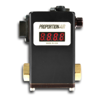
VOLTAGE COMMAND VALVES
All voltage command QB's use common mode voltage, meaning the DC
Common pin (Pin 1) is the common reference for both power and command.
Pin 1 is used as both the command signal common and power supply
common. The following diagram shows the proper connections.
CURRENT COMMAND VALVES
All current command QB's use a differential current loop scheme (not
isolated), meaning current flow is from Pin 4 to Pin 2 on the QB valve. Some
applications may require the common of the power supply that provides loop
power for the 4-20mA command to be tied to power supply common. The
following diagram shows the correct connection for conventional current flow.
PIN 4 {WHITE}
0-10 COMMAND (+)
PIN 1 {GREEN}
DC COMMON (-)
(POWER & COMMAND)
PIN 6 {BLACK}
DC POWER (+)
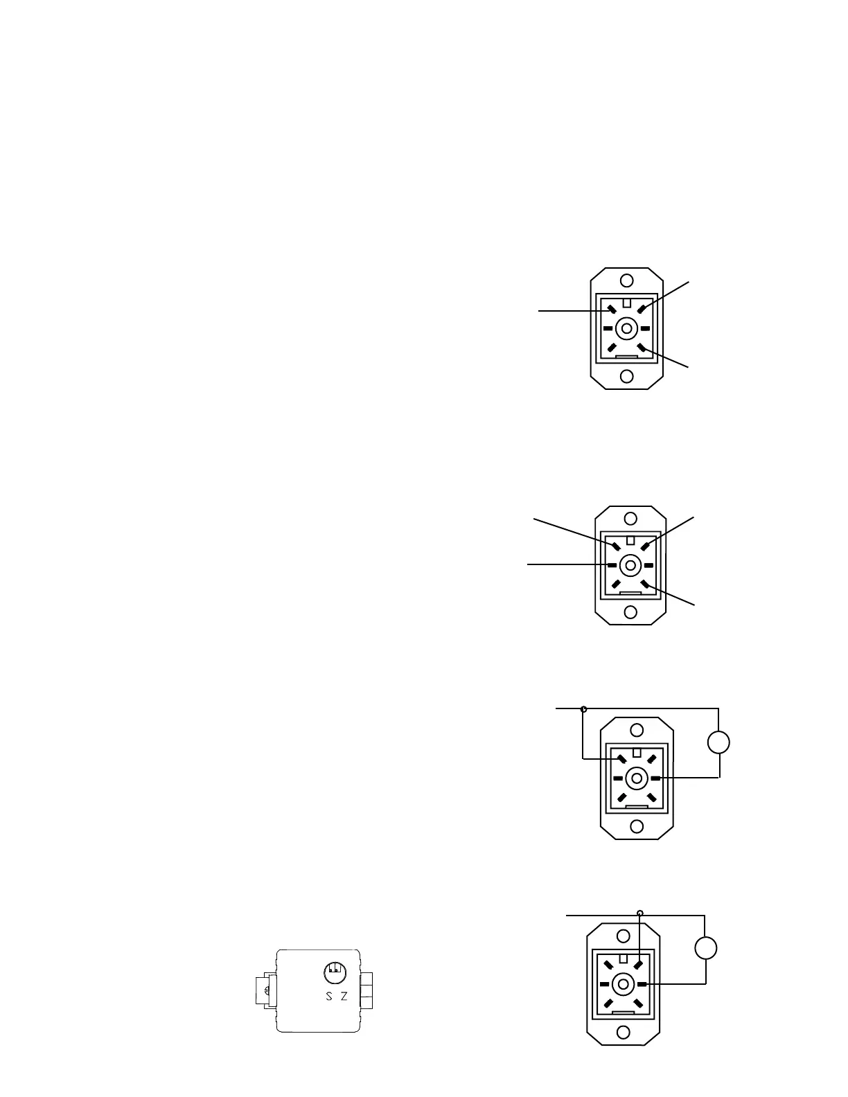
VOLTAGE MONITOR (EE OR IE)
Use the following wiring diagram for QB valves with a voltage monitor output.
PIN 1 {GREEN}
DC COMMON (-)
(POWER & COMMAND)
METER
-
+
PIN 5 {RED}
0-10V MONITOR (+)
V
CURRENT MONITOR SINKING(EC OR IC)
Use the following wiring diagram for QB valves with a current sinking monitor
output.
-
+
PIN 6 {BLACK}
DC POWER (+)
PIN 5 {RED}
4-20mA MONITOR (-)
MA
METER
PIN 2 {BLUE}
4-20MA COMMAND (-)
PIN 4 {WHITE}
4-20MA COMMAND (+)
PIN 1 {GREEN}
DC COMMON (-)
(POWER & COMMAND)
PIN 6 {BLACK}
DC POWER (+)
Figure 1
 Loading...