3/5
QBT Installation Guide - 3/22/2016 | SSS
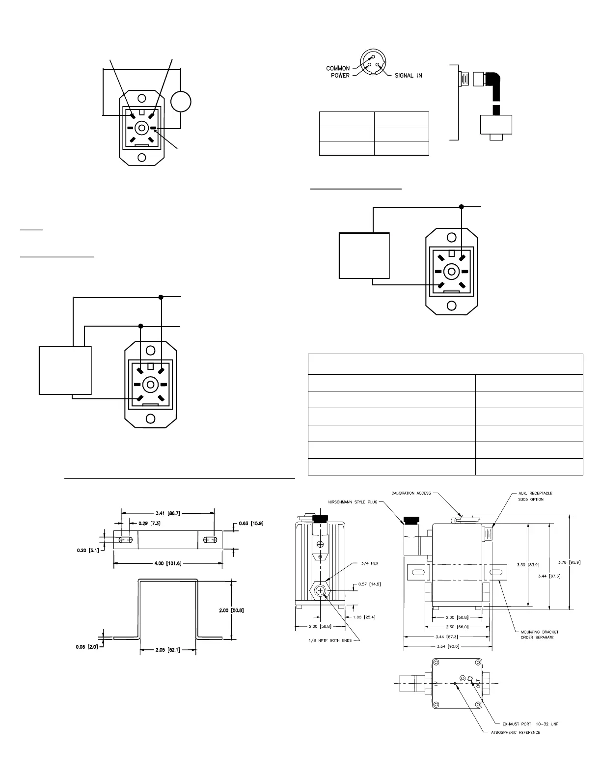
DIMENSIONS in [mm]
MOUNTING BRACKET
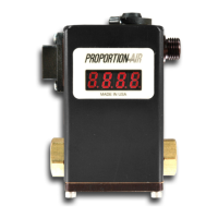
QB2 SECOND LOOP CONNECTIONS
All QB2 valves are designed to accept a 0-10 volt second loop input signal,
unless ordered with special option C2 (4-20 mA second loop input).
Reference the following wiring diagrams for details.
Standard QB2 valves
Second loop signal is wired into the main electrical connector.
PIN 3 {BROWN}
2ND LOOP IN (-)
PIN 6 {BLACK}
DC POWER (+)
3-wire
transducer
w/ 0-10 Vdc
output
PIN 1 {GREEN}
DC COMMON (-)
(POWER & COMMAND
PIN 6 {BLACK}
DC POWER (+)
PIN 1 {GREEN}
DC COMMON (-)
METER
-
+
PIN 5 {RED}
SIGNAL OUT
MA
CURRENT SOURCING MONITOR (ES OR TS)
QB2-C2 option valves
PIN 3 {BROWN}
2ND LOOP IN (-)
PIN 6 {BLACK}
DC POWER (+)
2-wire
transducer
w/ 4-20 mA
output
QB2-3D OPTION VALVES
Second loop signal is plugged into auxiliary receptacle on opposite side.
QB2-3D
Proportion-Air
DSY pressure
transducer
H23 COLOR CODE
RECEPTACLE
WHITE
SIGNAL IN
BLACK
DC POWER
GREEN
DC COMMON
RATED INLET PRESSURE FOR STANDARD QBS VALVES
TABLE 1
MAX. calibrated pressure: Max. inlet pressure:
Vacuum only 5 PSIG
Vacuum up to 10 PSIG 15 PSIG
10.1 up to 30 PSIG 35 PSIG
31 up to 100 PSIG 110 PSIG
101 up to 150 PSIG 165 PSIG
 Loading...