Table of Contents
Front and Rear Panel ........................................................................... 1
Remote Control.... ............................................................................... 2
Connections.........................................................................................3
First Time Installation........................................................................... 3
Troubleshooting...................................................................................8
Technical Specifications.......................................................................8
Front and Rear Panel
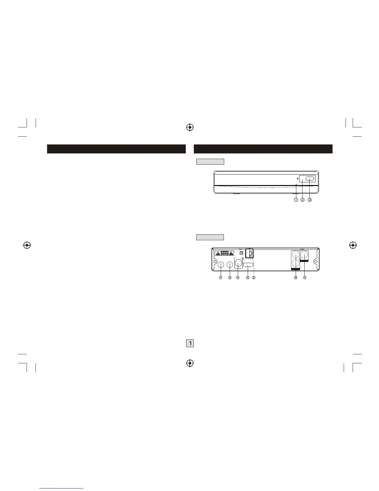
1. Front panel
1. STANDBY INDICATOR: Used to visually show power state of the set
top box, the LED will turn red if the set top box enter standby mode.
2. REMOTE CONTROL SENSOR: Used to receive the signal from the
remote control.
3. USB: Data input from USB storage devices.
2. Rear panel
1. RF I N :
2. RF LOOP THROUGH: This socket will bypass the RF signal to either
your TV or another video system.
3. COAXIAL: This socket connects to a coaxial socket on your surround
sound system.
4. HDMI OUT This socket connects to HDMI in device.
5. MAINS CABLE: This is used to connect to your main power supply.
6. AUDIO L/R: This socket allows you to connect your Set Top Box to
receive the Audio L/R signal.
7. VIDEO OUT:
Connect the AIR antenna or CATV cable here.
(if the cable provider is passing through 8VSB signal.)
This socket output composite video signal.
L
VIDEO
VIDEO OUT
R
AUDIO OUT
COAXIAL
DIGITAL
AUDIO
RF LOOP
THROUGH
RF IN
HDMI OUT
100-240V~
50/60Hz