P.4
Data Sheet: QPS-QSG
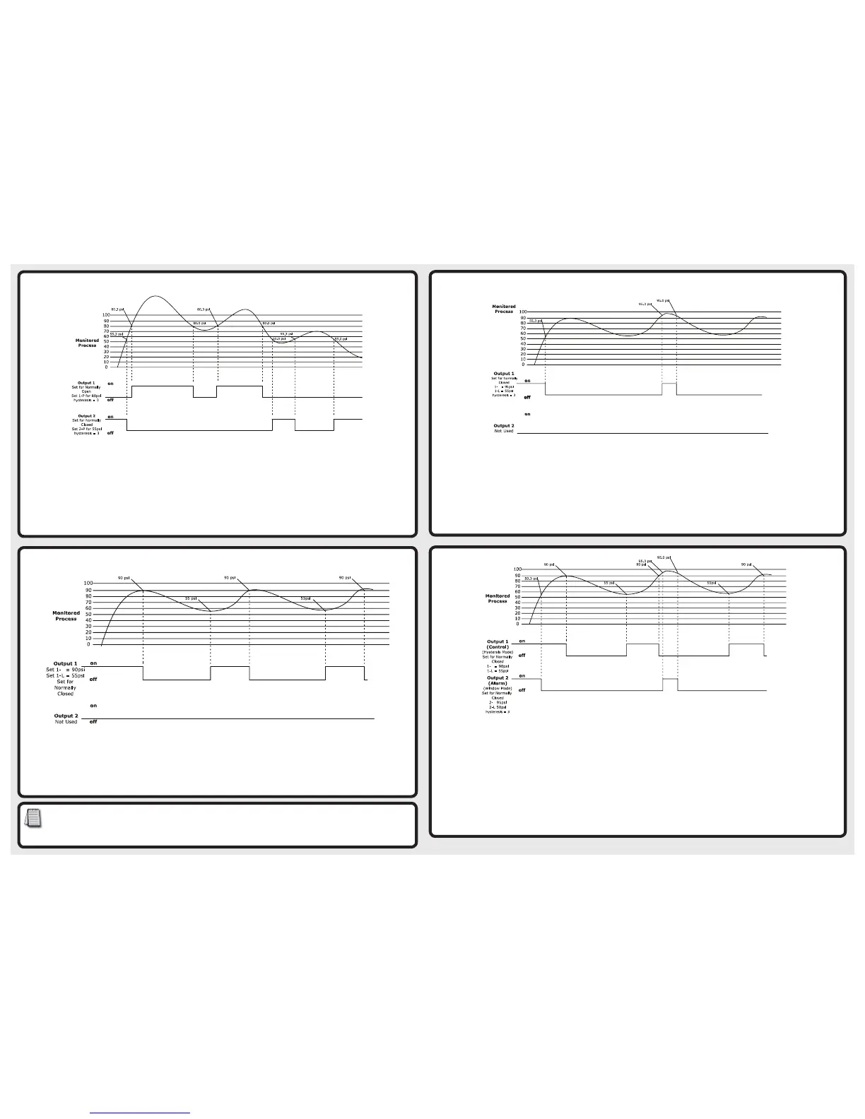
Window Mode: In the example below the output will change state when the measured pressure increases to 55.3psi (1-L SV + HYS)and will
change state again when the pressure increases to 90.3psi (1-H SV + HYS). As the measured pressure decreases back to 90psi (1-H SV) the output
will change state and will change state again when the pressure decreases to 55psi (1-L SV). Each digital output can be individually set.
Using Hysteresis Mode to control the pressure in a tank
Hold ; button for 2-3 seconds until display changes.
Verify 0T1 is set to HYS, if not use the ,. to change and press ; button.
Verify 0T2 is set to EASY, if not use the ,. to change and press ; button.
Verify noC is set to 1C2o, if not use the ,. to change and press ; button.
Press and hold the ; button until the display changes to show the Setpoint and Process values.
Using the ,. set the output 1 1-H level to 90psi.
Briefly press and release the ; button to change to 1-L and set it to 55psi.
Hysteresis Mode: When the measured pressure is greater than the Hi setpoint, the output will change state. When the measured pressure
is less than the Lo setpoint, the output will change state. Each digital output can be individually set.
Using EASY Mode to Set up a Simple Alarm
Hold ; button for 2-3 seconds until display changes.
Verify 0t1 is set to easy, if not use the ,. to change and press ; button.
Verify 0T2 is set to EASY, if not use the ,. to change and press ; button.
Verify noC is set to 1o2C, if not use the ,. to change and press ; button.
Press and hold the ; button until the display changes to show the Setpoint and Process values.
Using the ,. set the output 1 ON level for 1-P to 80psi.
Briefly press and release the ; button to change to 2-P and set the output 2 ON level to 55psi.
Hold ; button for 4-5 seconds until display changes to Pro.
Press the ; button 3 times so that HYS is on the display.
Verify the value 3 is in the lower display, if not use the ,. to change and press ; button
Press and hold the ; button until the display changes to show the Setpoint and Pressure copy values.
Easy Mode: When the measured pressure is greater than pressure setpoint plus the hysteresis setting (SV+hysteresis), the output will
change state. When the measured pressure is less than the pressure setpoint (<SV), the output will change state. Each digital output can
be individually set.
Copyright 2017, Automationdirect.com Incorporated/All Rights Reserved Worldwide
H
Hysteresis is defined as: The lag in response of the output in reacting to changes in the process affecting it. For example Setpoint
1-P is set to 80 PSI for output 1 but the output does not change state when the pressure is increasing until the actual pressure
reaches 80.3 PSI (1-P+hysteresis), the output will then change back to its neutral state once the pressure drops below the Setpoint
of 80 PSI. This function known as Hysteresis is used to prevent the outputs from chattering if the process pressure were to hover
close to the Setpoint.
H
H
Using Hysteresis mode to control the pressure in a tank and window mode to generate an alarm
Wire the QPS using the connection diagrams supplied.
Hold ; button for 2-3 seconds until display changes.
Verify 0T1 is set to Hys, if not use the ,. to change and press button.
Verify 0T2 is set to WCMP, if not use the ,. to change and press button.
Verify noC is set to 1C2C, if not use the ,. to change and press button.
Press and hold the ; button until the display changes to show the Setpoint and Process values.
Using the ,. set the output 1 1-H level to 90psi.
Briefly press and release the ; button to change to 1-L and set it to 55psi.
Briefly press and release the ; button to change to 2-H and set it to 95psi.
Briefly press and release the ; button to change to 2-L and set it to 50psi.
Hold ; button for 4-5 seconds until display changes to Pro.
Press the ; button 3 times so that Hys is on the display.
Verify the value 3 is in the lower display, if not use the ,. to change and press ; button.
Press and hold the ; button until the display changes to show the Setpoint and Process values.
Hysteresis & Window Modes of operation for control and alarming
Using Window Mode to create alarm condition
Hold ; button for 2-3 seconds until display changes.
Verify 0T1 is set to wCmp, if not use the ,. to change and press ; button.
Verify 0T2 is set to EASY, if not use the ,. to change and press ; button.
Verify noC is set to 1C2o, if not use the ,. to change and press ; button.
Press and hold the ; button until the display changes to show the Setpoint and Process values.
Using the ,. set the output 1 1-H level to 95psi.
Briefly press and release the ; button to change to 1-L and set it to 55psi.
Hold ; button for 4-5 seconds until display changes to Pro.
Press the ; button 3 times so that Hys is on the display.
Verify the value 3 is in the lower display, if not use the ,. to change and press ; button
Press and hold the ; button until the display changes to show the Setpoint and Process values.
 Loading...