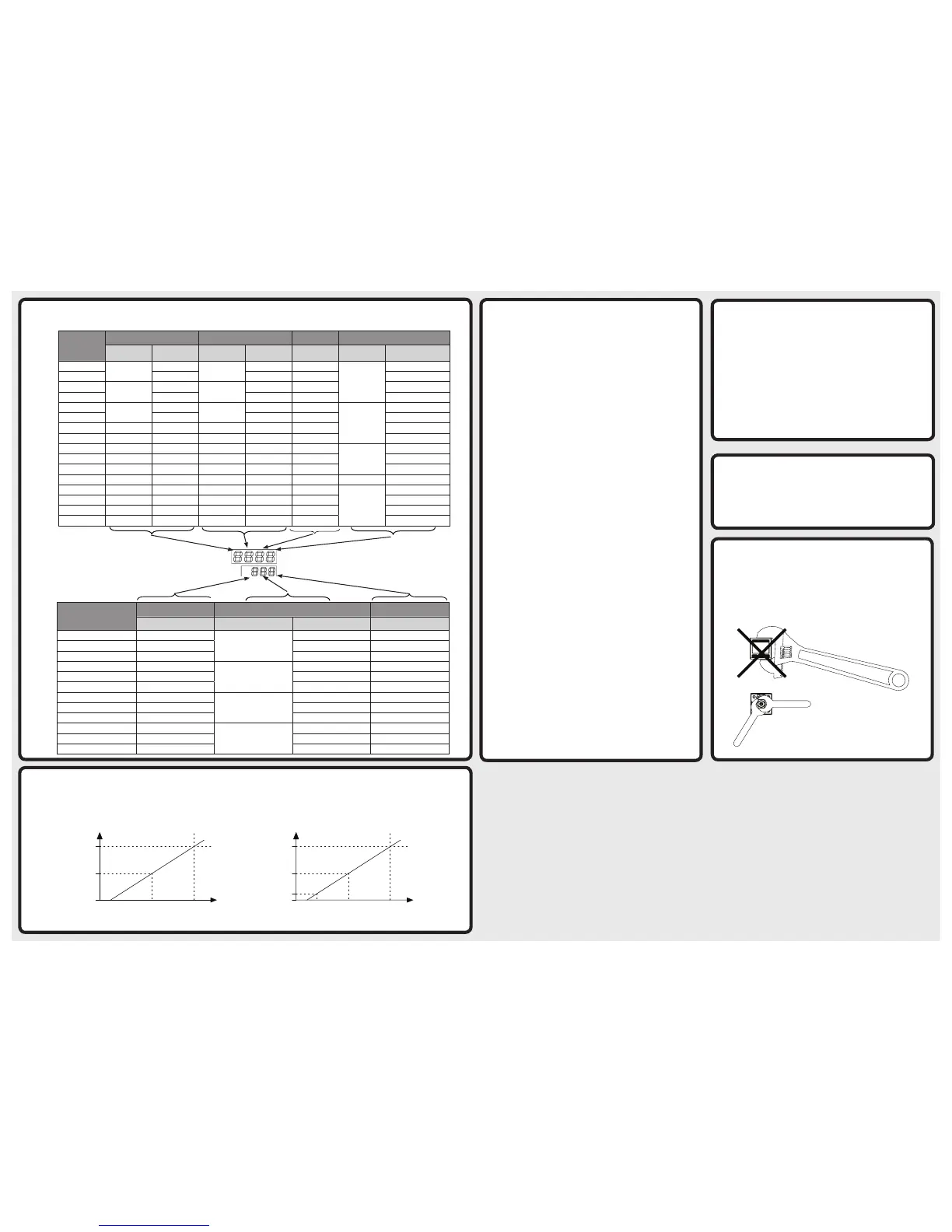
0psi 65.3psi
5.45mA
0psi
Process Connection
Use a suitable thread sealant Teflon® tape. Do not use liquid thread
sealant. Always tighten with an open end or adjustable wrench on
the wrench flats. Never use any part of the pressure gauge to tighten
other than the wrench flats that are on the gauge socket. Failure to
do so will severely damage the pressure gauge.
OK
SET
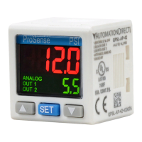
ProSense PSI
CODE (Pro Setup Mode Parameter Cod)
CODE provides a quick method to determine the settings of the QPS parameters (Factory Default 0000 302)
Locking the Keys
Lock On: Press ; and . together for 2 seconds until
lock
on
is
displayed. You will then see the display of pressure value (PV) and
setpoint value (SV).
Lock Off: Press ; and , together for 2 seconds until
lock
off
is
displayed. You will then see the display of pressure value (PV) and
setpoint value (SV).
Lock Display: Press any key in the key locking mode, and you will see
the display of pressure value (PV) and lCk (SV). Release the key and
the PV and SV will return to original values.
QPS is able to copy the parameters from one
device to another.
Electrical connection for copying parameters:
Connect Pin 2 (black) on master to Pin 3 (white) on slave; Pin 3
(white) on master to Pin 2 (black) on slave; Pin 5 (blue) on master
and slave to COM on power supply; Pin 1 (brown) on master and
slave to +24V on power supply.
Setup for copying paramters:
Slave device: In the “Run Mode”, press ; for more than 4 seconds
and release the key after you see
pro
set
. You are now in “Pro Setup
Mode”. Press ; 7 times and find the parameter for setting up the
copy function (See Pro Setup Mode chart). Use ,. to select
Cp-s
Cpy
(CP-S refers to Copy-Slave).
Master device: In the “Run Mode”, press ; for more than 2
seconds and release the key after you see
pro
set
. You are now in the
“Pro Setup Mode”. Press 7 times and find the parameter for setting
up the copy function (See Pro Setup Mode chart). Use ,. to
select
Cp-m
Cpy
(CP-M refers to the Copy-Master).
Next, press ; for more than 2 seconds and return to the “Run
Mode”.
Now you will see Cp-m on the display and CP-S on the slave
device, indicating that the two devices have been connected. In the
lower display int you will see numbers counting up, referring to
the number of parameters transmitted successfully between the two
devices.
Once the copy of parameters completes, you will see
Cp-m
ok
on the master device and
Cp-s
ok
on the slave device.
After the copy is complete, power the units off and re-connect them
according to the wiring diagram.
Resetting Zero Pressure:
Remove pressure from device before starting.
In the “Run Mode”, press ,. simultaneously, and you will see
0000
adj
. The zeroing will start. Release the keys to end the zeroing
sequence.
Code
1
st
digit 2
nd
digit 3
rd
digit 4
th
digit
OUT1 mode N.O./N.C. OUT2 mode N.O./N.C.
Output Response
Time
Color Switching Color Display
0
Easy
N.O.
Easy
N.O. 2ms
Red when ON
OUT1
1
N.C. N.C. 4ms OUT2
2
Hysteresis
N.O.
Hysteresis
N.O. 10ms OUT1 and OUT2
3
N.C. N.C. 30ms OUT1 or OUT2
4
Window
N.O.
Window
N.O. 50ms
Green when ON
OUT1
5
N.C. N.C. 100ms OUT2
6
– – – – 250ms OUT1 and OUT2
7
– – – – 500ms OUT1 or OUT2
8
– – – – 1,000ms
Red
OUT1
9
– – – – – OUT2
A
– – – – – OUT1 and OUT2
B
– – – – – Red OUT1 or OUT2
C
– – – – –
Green
OUT1
d
– – – – – OUT2
E
– – – – – OUT1 and OUT2
F
– – – – – OUT1 or OUT2
Code
6
th
digit 7
th
digit 8
th
digit
Pressure Unit Display Response Time SV/Setup Item Display Hysteresis Setting
0
kPa or MPa
100ms
Standard 1
1
kgf/cm² Off 2
2
bar Unit 3
3
psi
250ms
Standard 4
4
mm Hg or cm Hg Off 5
5
inch Hg Unit 6
6
–
500ms
Standard 7
7
– Off 8
8
– Unit –
9
–
1,000ms
Standard –
A
– Off –
B
– Unit –
QPS Display
 Loading...