EasyManua.ls Logo

Proteco Q60A User Manual

Proteco Q60A
6 pages
To Next Page IconTo Next Page
Page #1 background imageLoading...
Page #1 background image
A
B lower level menu button
C button to increase or change to yes (si)
D button to decrease or change to no
F1 230V fuse 5A
F2 2 1,6 A
F3 1 1,6 A
F4 24V fuse (self-restorable) 1,6A
F5 24V fuse (self-restorable) 0,65A
DISPLAY 7 SEGMENTS Display
M1 radio/aerial terminal block
M2A/M2B Controls and safety devices terminal blocks
M3 motors terminal block
M4 main power terminal block
earth connections
MR radio unit
CN electrolock interface pcb connector
Z2 filter
K1/ K2 motors relay
K3 blinker relay
VI Primary Varistor
V2 Secondary Varistor
top level menu button
cocoon fusesfuse
cocoon fusesfuse motor
motor
A B C
CONTROL UNIT COMPONENTS
06_prof._ Gb_2010
Button BButton BButton BButton BButton B
PC
P
C
Show stored codes
New remote control
code acquisition
Remote control code
acquisition with
STOP function
Remote control code
acquisition with
PEDESTRIAN function
Delete ALL remote
control codes
FUNCTIONSCODE
BUTTON B BUTTON B
Only
1 Motor
2 Motor
FUNCTIONSDISPLAY
I
2
FUNCTIONSCODE
P
S
P
P
Press & hold button C
to set defaults for
LEADER, ACE or SHARK.
Press & hold button C
to set defaults for
ADVANTAGE
ADVANTAGE MOTOR DEFAULTS
WHEELER DRIVE DAFAULTS
Press & hold button C
to set defaults for
WHEELER
Button BButton BButton B
P
A
A
Button AButton AButton AButton AButton A
PARAMETERS
STAND BY
TOP LEVEL MENU
RADIO
DEFAULT
SEQUENTIAL
PROGRAMMING
A
S
PARAMETERS
B use button B to move to next parameter
C use button C to INCREASE a numeric value or change NO to YES
D use button D to DECREASE a numeric value or change YES to NO
To save changes and to ensure that they are not lost when power is
removed, use button B to step through parameter, the press and hold
button C until the display reverts to idle display .
US
I
2
IF
2
F
F
I
2
5
5
Motor 1 working time
0 99
21 13 9
Motor 2 working time
0 99
21 13 9
Motor 1 Torque
8 19
14 10 12
Reversing stroke NO NO NO
Motor 2 Torque
8 19
19
14
19
10
19
12
Photocells test
SOFT START
SI
SI
NO
SI
SI
NO
SI
SI
NO
Press & hold
C to SAVE changes
button
Press
to ABANDON changes
button D
Electro lock NO NO SI
Motor 1
deceleration time
0 (N1 - 2”)
7 4 4
Motors test SI NO SI
Multi occupation NO NO NO
Motor 2
deceleration time
0 (N2 - 2”)
7 4 4
Deceleration on SI SI SI
Automatic closing
step by step
SI SI SI
Motor power during
deceleration
10 19
Lock pulse time
0=½ seconds, 1= 1 secs.
2=1½ secs. Etc........
0 0 0
Pre blinking
NO NO NO
Motors’ closing
differential time delay
0 N2
Motors’ opening
differential delay time
0 (N1 - 1)
3
3
3
3
2
2
Only one motor
NO NO NO
Button B Button B Button B Button B Button B Button B Button B Button B Button B Button B Button B Button B
OP
Button B Button B Button B Button B Button B Button B Button B Button B Button B Button B
Button B
IP
2P
E
P
4P
5P
6
6
P
P
Delay time before
automatic closing
0 99
3 3 3
P
Pedestrian
opening time
0 (N1 - 1)
7 7 3
7P
8P
P
US
standard
default
values
standard
default
values
wheeler
default
values
wheeler
default
values
advantage
default
values
advantage
default
values
TIMESDISPLAY
FUNCTIONS
P
P
S
P
S
P
P
P
DISPLAY SIGNALS
Opening
Closing
Delay time before
automatic Closing
DISPLAY
8. 8.
Decrease time
or change to NO
BUTTON A
BUTTON B
BUTTON C
BUTTON D
A
B
SI
NO
C
D
_
+
Move from the top
level menu to the lower
level menu
Cycle round the top
level menu
Increase time
or change to YES
SELF-RESTORABLE FUSE 24V
IMPORTANT:
restore itself after few seconds.
If a temporary short circuit occurs the fuse will
In case of a permanent short circuit, cut the main power
off, remove the terminal blocks 2A and 2B, wait few
seconds and then power the unit again.
The fuse will be automatically restored.
Find and remove the short circuit cause before plugging
the terminal blocks in.
I
I
Proteco S.r.l. Via Neive, 77
12050 Castagnito (CN) ITALY
Tel. +39 0173 210111 - Fax +39 0173 210199
www.proteco.net - info@proteco.net
Q60A/R
CONTROL UNIT
FOR SWING GATE
SINGLE
OR DOUBLE LEAF 230V
RED
RED
BLACK
BLACK
24V
DISPLAY
AC
AC
V1
V2
F2 F1
F3
M 2a M 2b
1 2 3 4
19 20
7 8 9 10 11 12
8. 8.
M 4
A
B
SI
NO
C
D
_
+
K1
K2
K3
13 14 15 16 17 18
M 3
Z2
230V
N
L
A B C
Trasformer
230V / 23V
F4
F5
EXTERNAL
RADIO
PANEL
Red
Black
White
Aerial
EXTERNAL RADIO PANEL
THE RADIO PANEL CAN ALSO BE PLACED
INSIDE THE BLINKER TO FURTHER IMPROVE
THE RADIO RANGE
CN
Question and Answer IconNeed help?

Do you have a question about the Proteco Q60A and is the answer not in the manual?

Proteco Q60A Specifications

General IconGeneral
BrandProteco
ModelQ60A
CategoryControl Unit
LanguageEnglish

Summary

Q60A/R Control Unit Overview

Control Unit Components Identification

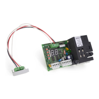
Lists and describes the various components of the Q60A/R control unit, including buttons, display, and terminals.

Parameter Navigation and Adjustment

Explains how to navigate and adjust control unit parameters using the unit's buttons.

Display Signals and Status Interpretation

Details the meaning of signals displayed on the control unit's digital display.

Remote Control and Function Management

Covers procedures for managing remote controls and accessing unit functions like code storage.

Default Setting Procedures for Motors

Outlines how to set default configurations for different motor types like Advantage and Wheeler.

Programming and Diagnostics Guide

Radio Receiver Programming

Guides on deleting, storing, and managing radio remote control codes for the receiver.

Control Unit Parameter Programming

Details standard and sequential methods for programming control unit parameters.

Sequential Programming for Gate Operation

Step-by-step instructions for sequential programming of single and double leaf gates.

Self-Diagnosis Display Messages

Explains error codes and messages displayed during the control unit's self-diagnosis.

Special Functions Configuration

Describes how to configure special functions like automatic closing and multi-user modes.

Terminal Block Connections and Wiring

General and Earth Terminal Connections

Details general wiring practices and earth terminal connections for the system.

Terminal Block 2 Wiring

Explains the functions and wiring for terminal block 2, covering inputs and safety devices.

Terminal Block 3 Motor Wiring

Details wiring for Motor M1 and M2 connections, including capacitor connections.

Terminal Block 4 Power Input

Covers power input connections for the control unit, specifying voltage and frequency.

Wiring Schemes for Various Configurations

Basic and Special Command Wiring

Illustrates wiring for Start, Pedestrian Start, Timer, and Emergency Stop functions.

Motor Connection Schemes

Provides wiring diagrams for Leader and Ace motor types in different gate configurations.

Single Motor Wiring

Shows wiring diagrams for single motor installations, both right and left configurations.

Advanced Wiring and Photocell Integration

Shark and Wheeler Motor Wiring

Wiring diagrams for Shark and Wheeler motor types in various gate opening configurations.

Single Motor Wiring Diagrams

Detailed wiring schemes for single motor setups, covering right and left side installations.

Photocell and Electro-Lock Connections

Photocell Connection in Closing Phase

Illustrates how to connect photocells for safety during the closing phase.

Photocell Connection in Opening Phase

Details the wiring for connecting photocells for safety during the opening phase.

Electro-Lock Interface Wiring

Explains how to connect an electro-lock via the MEL interface and related parameter settings.