-9-
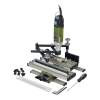
GE 20 engraving device
The GE 20 engraving device is the ideal instru-
ment for engraving ornamentations, letters or
numbers on metal or plastic. Signs can therefore
be created, small valuables decorated and indi-
vidual embellishments created on jewellery with
ease.
Retailers keep abroad selection of stencils in
stock for this purpose, including every conceiv-
able kind of template for plant ornamentation,
animals, coats of arms, etc. Stencil templates
can, of course, be individually created wherea
freely invented fig-ureistobeengraved. In this
case, no limitations areplaced on creativity,and
inspiration can be found practically anywhere!
Drawing stencils areprovided for creating letters
and numbers. These arefixed in position using a
guide rail included in the scope of delivery.A
maximum of 14 characters can be fitted here
adjacent to each other,morethan enough for
nameplates or similar.The stencils aretraced pre-
cisely with the guidemarker on the GE 20 engrav-
ing device which, in turn, is guided with acom-
fortable ball handle.
This movement is reduced and transmitted to the
clamped milling tool. The reduction ratio can be
fixed at 2:1, 3:1, 4:1 or 5:1 by simply adjusting
two screws.
Our step clamp set (article number 24256) is ideal
for clamping and aligning the workpiece to be
engraved. This is described in detail in chapter
“Accessories” later in this manual.
Further information on useful accessories is also
contained in this section. We hope you enjoy
working with the engraving device!
Scope of delivery:
•GE20engraving device
•Allen key 1.5 mm
•Allen key 3mm
•Allen key 5mm
•Screwdriver HX 2.5
•Letter strip
•Letter set
•Fastening set for letter strip
Assembly of the GE 20 engraving device
Fitting the guide marker:
For packaging reasons, the guide marker is not
prefitted, but assembly is very simple, as illus-
trated in Fig. 1:
1. Unscrew the ball handle 1and stop 2fromthe
guide marker 3
2. Screw the guide marker 3into the threaded
hole 4provided for this purpose
3. Screw the ball handle 1and stop 2into place
again
Fitting the guide arm:
1. Insert axle 1through the opening in the guide
arm 2(see Fig. 2)
2. Insert axle 1together with the guide arm into
the hole on the T- slot table 3intended for this
purpose (see illustration). Prior to this, fit the
spacer sleeve 4tothe axle 1. Ensurethat the
axle is tur ned so that the screw 5makes con-
tact with the flat position on the underside of
the axle!
Selection of reduction ratio
Four reduction ratios can be configured by vary-
ing the lever ratios on the guide arm: 2:1 (A), 3:1
(B), 4:1 (C) and 5:1 (D). Only varying combina-
tions of positions of both elements of the guide
arm need to be configured for this purpose.
This is really easy.Simply unscrew the knurled
screw 1(Fig. 3), select the desired position for the
arms and screw the knurled screw in again.
Note that the arms arelabelled with numbers, as
shown in the illustration!
We have labelled the respective hole combina-
tions with letters in the illustration which corre-
spond to the details specified above in the text.
For example, Fig. 3illustrates the configuration
for areduction from 2:1 (i.e. the en-graving is half
the size of the original here).
On the other hand, Fig. 4illustrates an example of
areduction of 5:1.
GB
 Loading...