4
P Z 7
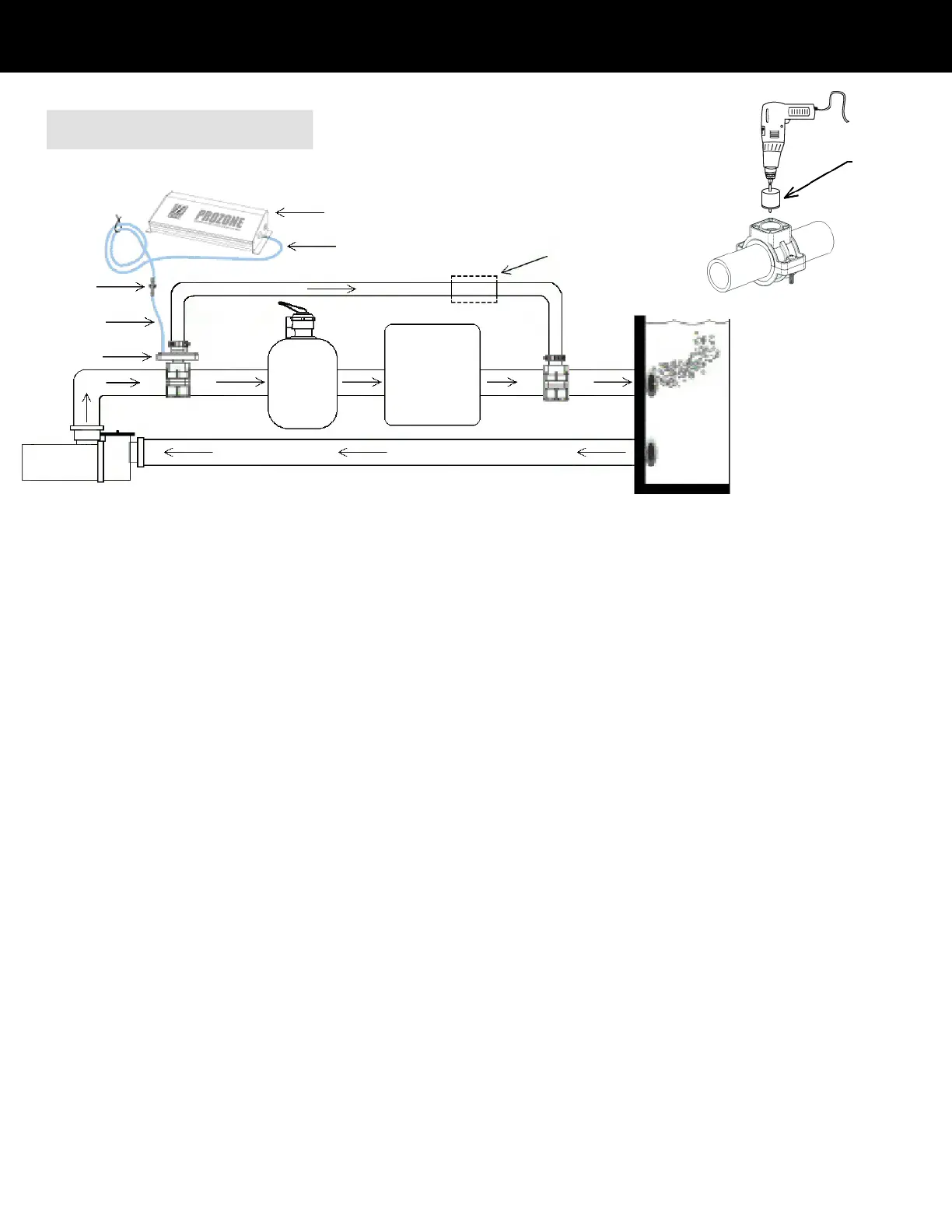
Saddle Clamp Installation
CAUTION: Make sure the voltage is the same as prescribed on the side of the Prozone ozone generator. Overvoltage will void
customer warranty.
7/8” Hole Saw
INSTALLATION ASSEMBLY USING
P15 SADDLE CLAMP KIT
1.
2.
3.
4.
5.
6.
7.
8.
9.
10.
11.
12.
13.
14.
Turn pump OFF.
Locate section of existing plumbing in which you choose to install the ENTRANCE leg of the bypass. Location should be in any
accessible area after the pump, but before the filter.
Install Saddle Clamp Top & Bottom, (and adapters if needed), without Bushing, (this will be used as a guide for your installation hole).
Drill a 7/8” hole through one wall of the pipe, using power drill, being careful not to drill too deep to avoid penetrating the opposite side
of the plumbing.
Locate section of existing plumbing in which you choose to install the EXIT leg of the bypass. Location should be in any accessible
area after the filter, and heater (if equipped).
Repeat steps 3 & 4.
Remove both Saddle Clamp Assemblies.
Using components listed, mount one Saddle Clamp Assembly on Entrance bypass location with the INLET side of the Venturi Injector
mounted in the Saddle Clamp Bushing, (ozone ports should be facing upward). Tighten both screws.
Using components listed, mount the other Saddle Clamp Assembly on Exit bypass location with the ½” x 3” PVC pipe mounted in the
Saddle Clamp Bushing. Tighten both screws.
Attach one end of ¾” clear hose to Venturi Injector and secure with a metal clamp. Attach other end of ¾”clear hose to ½” x 3” PVC
pipe and secure with a metal clamp.
Mount the PZ7 Ozone Generator on a wall or surface at least 1 foot above maximum water level to prevent water from contacting the
electrical equipment. Unit orientation will not affect performance.
Electrical Installation: Your Prozone PZ7 System is designed to operate on either 120 or 240 VAC, 50/60 HZ. Wire Prozone Ozone
Generator system to circulation pump switch or timer. Prozone system and circulation pump should be started simultaneously. Use
N.E.C. or local code grounding and installation procedures for swimming pool equipment.
NOTE: If your filtration system uses a Diatemateous Earth (DE) or cartridge filter, install a ¾” Ball Valve (not included) in the ¾” Hose on the
output side of the Venturi Injector as shown. This allows the bypass to be closed when back flushing or adding DE. It may be necessary to
install a Ball Valve (not included) in the main line between the Entrance and Exit of the bypass, (entire installation is moved after filter or heater
if equipped). The Ball Valve will need to be adjusted to ensure adequate flow through the bypass.
Pump
Filter
Heater
Pool
Bypass
Entrance
¾” Hose
Bypass
Exit
¼” Hose
Check Valve
¾” Ball Valve
(If using a DE filter)
Venturi Injector
¼” Hose
PZ7
Cut a 6” length of ¼” Polybraid Hose and connect one end to the open ozone port (Marked #1) on the Venturi Injector and the other
end to the OUTLET side of the Check Valve, (Make sure you can blow air through the Check Valve towards the Injector port). Secure
both ends with black plastic clamps.
Connect the remaining section of
¼” Polybraid Hose to the INLET side of the Check Valve and the other end to the barb on the side of
the PZ7 Ozone Generator. Secure both ends with black plastic clamps.
 Loading...