EasyManua.ls Logo

PS Engineering PM1000 User Manual

PS Engineering PM1000
7 pages
To Next Page IconTo Next Page
Page #1 background imageLoading...
Page #1 background image
200-190-0002 1 Rev. 2, Jan. 2001
9800 Martel Road
Lenoir City, TN 37772
PM1000
2-Place Intercom System
Operation and Installation Manual
FAA-Approved
TSO C50c
Document P/N 200-190-0002
Revision 2 Jan.1998
PS Engineering, Inc. 2001 ©
Copyright Notice
Any reproduction or retransmittal of this publication, or any portion thereof, without the expressed written permission of PS
Engineering, Inc. is strictly prohibited. For further information contact the Publications Manager at PS Engineering, Inc.,
9800 Martel Road, Lenoir City, TN 37772. Phone (865) 988-9800
PS Engineering Incorporated
PM 1000 FAA TSO Approved Intercom
Installation and Operation Manual
200-190-0002 2 Rev. 2, Jan. 2001
Section I General Information
1.1 Introduction
The PM1000 is an FAA-TSO approved, panel mounted, 2-place intercom system (ICS). Please read this
manual completely before installation to minimize the risk of damage to the unit and to become familiar with
all the features.
1.2 Scope
This manual contains installation and operational instructions for the following PS Engineering unit:
Model Description Part Number
PM1000 2-place intercom system 11900
1.3 Description
The PM1000 is a 2-place, panel-mounted intercom with individual volume and squelch controls for the pilot
and copilot positions.
A front panel mode switch allows the pilot to select one of two possible configurations:
"ISO" mode isolates the pilot from the intercom and connects to the aircraft radio. The copilot can continue
listen to entertainment without distracting the pilot. This position will not hear radio communications.
"ALL" mode places all headsets on a party line. Each one hears aircraft radio, entertainment and can use the
intercom.
The PM1000 has an automatic fail-safe interconnect to the aircraft radio. If power to the intercom is
disrupted, an internal relay will connect the pilot's headset to the aircraft radio. This allows continuous radio
communications. Note: The copilot will no longer hear aircraft radio when power is removed.
The LED shows green when power is applied to the unit.
An auxiliary input is provided, allowing the pilot and copilot the option to listen to music during flight.
During intercom activity, this music is automatically muted to allow communications without distraction.
When the activity ceases, the music returns to the original listening volume.
Note: the music is NOT muted during radio reception. During times when radio communication is vital, the
pilot should select “ISO” mode. Other occasions where radio is of lessor importance, it is possible to put the
intercom in the background by reducing the PM1000 volume. The pilot volume control doesn’t effect the
volume of the aircraft radio, so it can be adjusted to a more prominent level.
Both pilot and copilot have transmit capabilities over the radio. The PM1000 allows only the person who
presses their PTT to be heard over the aircraft radio. If both pilot and copilot press the PTT at the same time,
Question and Answer IconNeed help?

Do you have a question about the PS Engineering PM1000 and is the answer not in the manual?

PS Engineering PM1000 Specifications

General IconGeneral
BrandPS Engineering
ModelPM1000
CategoryIntercom System
LanguageEnglish

Summary

Section I General Information

Introduction to PM1000 Intercom

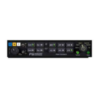
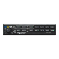
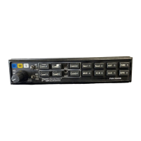
Provides an overview of the PM1000 as an FAA-TSO approved, panel-mounted intercom system.

Scope of PM1000 Manual

Defines the manual's purpose, covering installation and operational instructions for the PS Engineering PM1000 unit.

PM1000 Intercom System Description

Details the PM1000's features including individual controls, ISO/ALL modes, fail-safe radio interconnect, and auxiliary input.

PM1000 Approval Basis and Specifications

PM1000 FAA Approval Basis

Confirms the PM1000, part number 11900, is FAA-approved under TSO-C50c.

PM1000 Technical Specifications

Lists detailed technical specifications for the PM1000, including power, current, impedance, dimensions, and environmental ratings.

Equipment Required for PM1000 Installation

Enumerate the necessary external equipment not included with the PM1000 for a complete installation.

PM1000 License Requirements

States that no specific pilot or operator licenses are required for the PM1000's use.

Section II Installation Procedures

General Installation Information for PM1000

Provides initial installation guidance, mentioning included hardware, optional kits, and installer responsibilities.

Unpacking and Inspection of PM1000

Instructs users to inspect the unit for defects and verify all components in the parts kit upon receipt.

PM1000 Panel Mounting Procedures

Details the step-by-step process for mounting the PM1000 unit onto the aircraft instrument panel.

PM1000 Cable Harness Wiring

Covers wiring requirements, noise issues, and connections for the PM1000 intercom system.

Electrical Noise Issues in PM1000 Installation

Warns about potential noise from mic/headphone signals and recommends shielded cables and proper grounding.

PM1000 Power, Auxiliary, and PTT Connections

PM1000 Power Requirements

Specifies the voltage range and protection needed for the PM1000's power supply.

PM1000 Auxiliary Audio Input

Explains how to connect an entertainment device and its automatic muting feature during intercom activity.

PM1000 Optional Accessories

Discusses interfacing with expansion units for additional capabilities like crew mode.

External PTT Switch Configurations for PM1000

Details three configurations for connecting Push-To-Talk switches for radio transmission.

PM1000 Post-Installation Checkout

Provides a checklist for verifying correct installation and functionality after wiring is complete.

Section III PM1000 Operation

Adjusting PM1000 Volume Controls

Explains how to adjust the pilot and copilot volume controls for intercom and music.

Adjusting PM1000 Squelch Controls

Details how to adjust the VOX squelch controls for optimal performance and background noise reduction.

PM1000 Mode Selection (ISO/ALL)

Describes the center mode switch for tailoring intercom function to flight conditions.

PM1000 Optional Accessories and Expansion

Discusses interfacing with expansion units for additional capabilities like crew mode.

PM1000 Warranty and Service Information

PM1000 Factory Service and Returns

Outlines the process for obtaining factory service, including warranty details and return procedures.

Appendix A: PTT Modifications Guide

Provides instructions for modifying common PTT switches to ensure proper intercom function.

Appendix B: FAA Form 337 Instructions

Offers guidance and sample text for completing FAA Form 337 for PM1000 installation.

Appendix C & D: PM1000 Maintenance and Wiring

Appendix C: Continuing Airworthiness for PM1000

Defines the PM1000 as an 'on-condition' maintenance item and outlines inspection practices.

Appendix D: PM1000 Wiring Diagrams

Presents detailed wiring diagrams for the PM1000 unit and its connections to various aircraft systems.

Related product manuals