EasyManua.ls Logo

PSA Products homeguard HG1000 User Manual

PSA Products homeguard HG1000
25 pages
To Next Page IconTo Next Page
Page #1 background imageLoading...
Page #1 background image
MODEL HG1000
INSTALLATION AND USER MANUAL
SMOKE ALARM IONISATION DESIGN
IMPORTANT: READ ALL INSTRUCTIONS BEFORE INSTALLATION.
NO USER REPLACEABLE PARTS INSIDE THIS SMOKEALARM.
WARNING:
Disconnecting smoke alarm from mounting base and/or removing the 9V battery
will render this smoke alarm inactive.
240VAC MAINS POWERED SINGLE STATION AND/OR INTERCONNECTABLE
(24 UNITS) IONISATION SMOKE ALARM. 9V REPLACEABLE BATTERY
BACKUP . TEST AND HUSH CONTROL AND LOW BATTERY INDICATION.
SPECIFICATION
ELECTRICAL RATING: 240VAC 50Hz, 80mA per alarm and interconnectable to
24 alarms.
WARNING: THIS SMOKE ALARM MUST ONLY BE WIRED TO A
240Vac 50Hz SINE WAVE CURRENT SUPPLY.
THE SMOKE ALARM USES AN EXTREMELY SMALL AMOUNT OF A
RADIOACTIVE IN THE IONISATION CHAMBER.
1299-7201-01:_ 2014.5.7 10:40 AM Page 1
Question and Answer IconNeed help?

Do you have a question about the PSA Products homeguard HG1000 and is the answer not in the manual?

PSA Products homeguard HG1000 Specifications

General IconGeneral
BrandPSA Products
Modelhomeguard HG1000
CategorySmoke Alarm
LanguageEnglish

Summary

SMOKE ALARM IONISATION DESIGN

Important Installation Precaution

Emphasizes reading all instructions before installation.

SPECIFICATION

Power Supply Warning

Mandates wiring only to a 240Vac 50Hz sine wave current supply.

RECOMMENDED LOCATIONS OF ALARMS

General Placement Guidelines

Place alarms near sleeping areas, stairways, all floors, smokers' rooms, and appliance rooms.

INSTALLATION OF SMOKE ALARM

Orientation for Optimal Effectiveness

Proper orientation is critical to prevent decreased operational effectiveness.

MOBILE HOME INSTALLATION

Mobile Home Testing Reminder

Reminds users to test alarms after storage, before trips, and weekly.

FALSE ALARMS

Cooking and Combustion Particle Triggers

Cooking particles can trigger alarms if too close; Hush® Control is recommended near kitchens.

Responding to an Alarm

Check for fire first; if none, identify cause. Escape if fire is found.

INSTALLATION

Installer Qualification Warning

Installation must be performed only by qualified (licensed) electricians.

Wiring Instructions Safety

Installation must comply with SAA Wiring Rules - AS3000 for safety.

AC Power Connection Precaution

Do not connect the alarm on the base plate without AC mains power present.

WIRING AND INTERCONNECTION

Terminal Block Markings

Correct wiring to terminals A, S, N is crucial; incorrect wiring voids warranty.

Interconnect Terminal Warnings

Do not connect AC power or other devices to the S terminal; it will cause damage.

POWER AND MOUNTING INSTRUCTIONS

Inverter Power Warning

Do not use square wave or modified sine wave inverters; they can damage the alarm.

Dedicated Subcircuit Recommendation

Install on its own subcircuit to avoid interference and nuisance chirping.

Mounting Instructions

MOUNTING AND ALARM ATTACHMENT

Alarm to Mounting Plate Alignment

Align marks on plate and alarm, twist alarm to lock it in place.

TEST AND BATTERY BACKUP PROCEDURES

Test and Battery Backup Functionality

Alarm needs battery backup; test button activates alarms, including interconnected ones.

Alarm Tamper Resist Feature

Tamper-Resist Pin Removal

Tamper-resistant pin must be removed with pliers to change the battery or remove the alarm.

OPERATION, TESTING AND MAINTENANCE

LED Indicator Functions

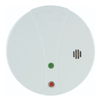
Explains the functions of the Red LED (stand-by, alarm) and Green LED (AC power).

False Alarm Hush Control Feature

Hush Feature Description

Temporarily desensitizes alarm for 5-15 mins by pressing Test/Hush button.

Hush Feature Usage Warning

Identify smoke source and ensure safety before using the Hush feature.

OPERATING AND ALARM CHARACTERISTICS

Operating and Alarm Characteristics Table

Details normal, alarm, and low battery modes with LED status and recommendations.

BATTERY INSTALLATION, REPLACEMENT AND TEST

Battery Backup Functionality

Uses 9V battery for backup; low battery indicator chirps and flashes Red LED.

Battery Replacement Procedure

Remove alarm from base, remove old battery, replace with new one.

Battery Installation Caution

Using incorrect batteries can cause malfunction, explosion, injury, or fire.

BATTERY HANDLING AND TESTING

Post-Installation Battery Check

Ensure detector is fully connected and Green LED is ON after reinstalling.

Battery Test

Weekly Testing Recommendation

Recommends weekly testing for ongoing reliability.

REPAIRS AND SERVICES

Radioactive Source Warning

Warning against tampering with the radioactive source within the unit.

DEVELOP AND PRACTICE A PLAN OF ESCAPE

WHAT TO DO WHEN THE ALARM SOUNDS

Alerting Children and Evacuation

Alert small children and leave immediately via escape plan.

Post-Evacuation Actions

Go to meeting place, call Fire Brigade from neighbour's, do not return until cleared.

INSTALLER PLEASE NOTE

WARNING: INSULATION TEST

Prohibition of Insulation Testing

Never perform insulation resistance tests on circuits with smoke alarms fitted.

Test Damage and Warranty Void

Testing can cause irreparable damage and void the warranty.

Weekly Testing Reminder

Recommends weekly testing for ongoing reliability.

COMPLIANCE AND STANDARDS

AS3786 Compliance Statement

States the smoke alarm has been tested and complies with AS3786 standards.