20
2
17
19
1
18
3
16
4
23
22
14
12
15
13
11
8
910
6
7
5
21
WARNING!
Do not overload engine stand beyond rated capacity. Overloading
can cause damage to or failure of the engine stand.
Always use stand on hard, level surface capable of sustaining the load. Use of
stand on other than hard level surfaces can result in stand instability and
possible loss of load.
Always lock rotational locking device before applying load. Assure that the load is
centered and secured to the mounting plate. Off center loads may make the load
and handle rotate in either direction when the rotational locking device is released.
TOOL FEATURES
Capacity.................................................................................................. 1,000 lbs.
Length......................................................................................................30-5/8 in.
Width .......................................................................................................30-1/2 in.
Height ....................................................................................................33-7/16 in.
SPECIFICATIONS:
Specifications are subject to change without notice.
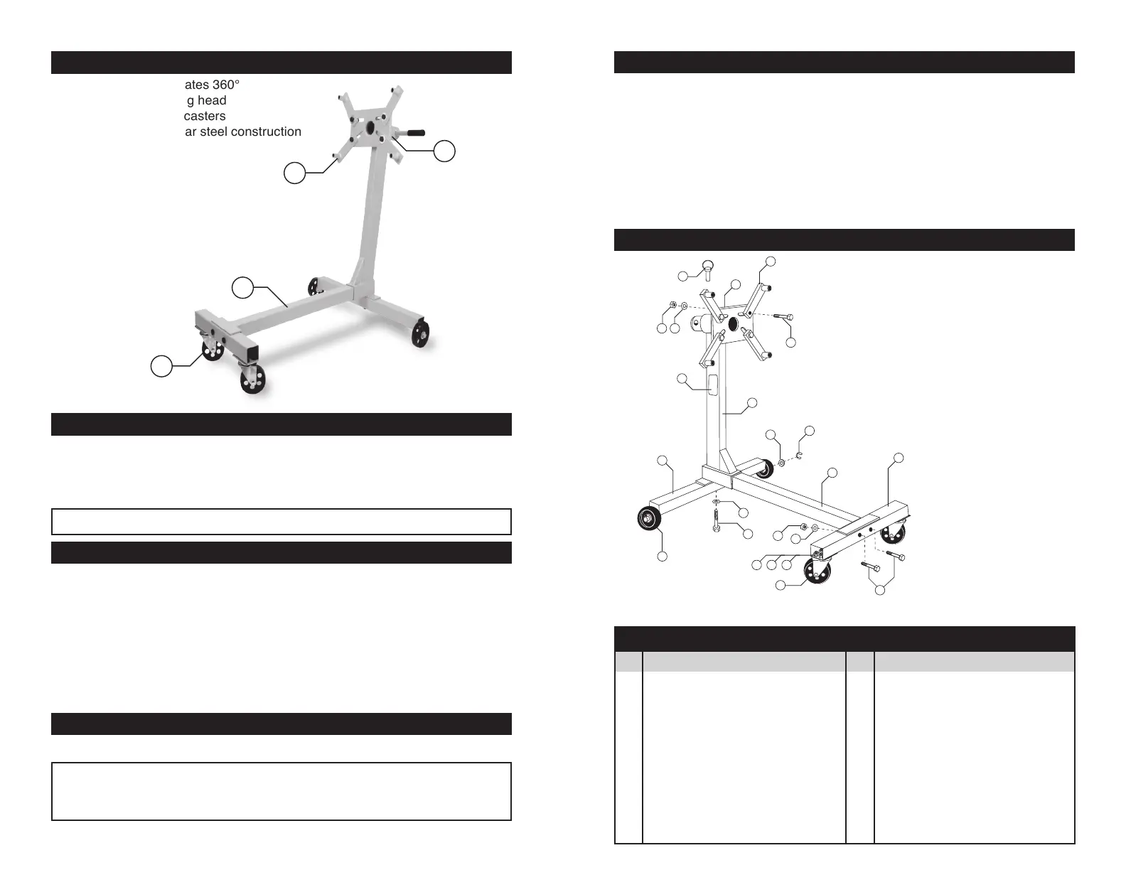
1. Head assembly rotates 360°
2. Adjustable mounting head
3. Heavy duty swivel casters
4. Heady gauge tubular steel construction
4
2
1
3
This instruction manual is intended for your benefit. Please read and follow the safety, installation, maintenance and troubleshooting
steps described within to ensure your safety and satisfaction. The contents of this instruction manual are based upon the latest
product information available at the time of publication. The manufacturer reserves the right to make product changes at any time
without notice.
SAFETY GUIDELINES / DEFINITIONS
WARNING: Read and understand this entire instruction manual before attempting to assemble, install, operate or maintain
this product. Failure to comply with the instructions may result in serious personal injury and/or property damage!
The following signal words are used to emphasize safety warnings that must be followed when using this product:
DANGER:
Indicates an imminently hazardous situation
that, if not avoided, WILL result in death or serious injury.
WARNING:
Indicates a potentially hazardous situation that,
if not avoided, COULD result in death or serious injury.
CAUTION:
Indicates a potentially hazardous situation that,
if not avoided, MAY result in minor or moderate injury.
NOTE: Indicates important information, which if not
followed, MAY cause damage to equipment.
SAFETY INFORMATION
ASSEMBLY INSTRUCTIONS
1. Attach main post (1) and center frame
(2) to rear frame (3) with bolt (4) and
washer (11) as shown in drawing.
2. Attach front frame (20) to center frame
(2) with bolts (21), washers (22) and
nuts (23).
3. Insert head mounting plate into collar
at top of main post and secure with
lock pin (6).
4. Attach mounting arms (7) to head
mounting plate with nuts, bolts &
washers (8), (9) & (10).
NOTE: Some parts may
be pre-assembled.
SAFETY INFORMATION
Read these safety warnings before operation.
WARNING! FAILURE TO HEED THESE WARNINGS MAY RESULT IN
LOSS OF LOAD, DAMAGE TO ENGINE STAND, AND/OR ENGINE STAND
FAILURE RESULTING IN PERSONAL INJURY OR PROPERTY DAMAGE.
PARTS LIST
1 Main Post .................................1
2 Center Frame ...........................1
3 Rear Frame ..............................1
4 Bolt, M12 x 75 lg. .....................1
5 Head Mounting Plate................1
6 Lock Pin ...................................1
7 Mounting Arms .........................4
8 Bolt M12 x 60 lg. ......................4
9 Flat Washer, M12 .....................4
10 Hex Nut, M12 ...........................4
11 Lock Washer, M12 ...................1
12 Bolt, M8 x 16 ............................8
13 Nut, M8 .....................................8
14 Caster Wheel .........................2
15 Lock Washer, M8 .....................8
16 Rear Wheel ..............................2
17 Flat Washer, M12 .....................4
18 Warning Label ..........................1
19 E-Ring ......................................2
20 Front Frame .............................1
21 Bolt, M10 x 60 lg. .....................2
22 Washer, flat, M10 .....................2
23 Nut, M10...................................2
No. Description Qty. No. Description Qty.
 Loading...