4
1. Use a qualied person to maintain the press in good condition. Keep it clean
for best and safest performance.
2. The maximum load is 12 tons. DO NOT exceed this rated capacity. Never
apply excessive force to a workpiece and always use the pressure gauge to
accurately determine the applied load.
3. Use this press for the purpose for which it is intended. DO NOT use it for any
other purpose it is not designed to perform.
4. Keep children and unauthorized persons away from the work area.
WARNING! PLEASE READ THESE SAFETY INSTRUCTIONS AND
WARNINGS. USE THE PRODUCT CORRECTLY AND WITH CARE FOR THE
PURPOSE FOR WHICH IT IS INTENDED. FALURE TO DO SO MAY CAUSE
DAMAGE TO PROPERTY AND/OR SERIOUS PERSONAL INJURY.
PLEASE KEEP THIS INSTRUCTION MANUAL SAFE FOR FUTURE USE.
1. Purge away air from the hydraulic system: open the release valve by turning it
counterclockwise. Pump several full strokes to eliminate any air in the system.
2. Check all parts and conditions, if there is any part broken, stop using it and
contact your supplier immediately.
BEFORE FIRST USE
IMPORTANT SAFETY INFORMATION
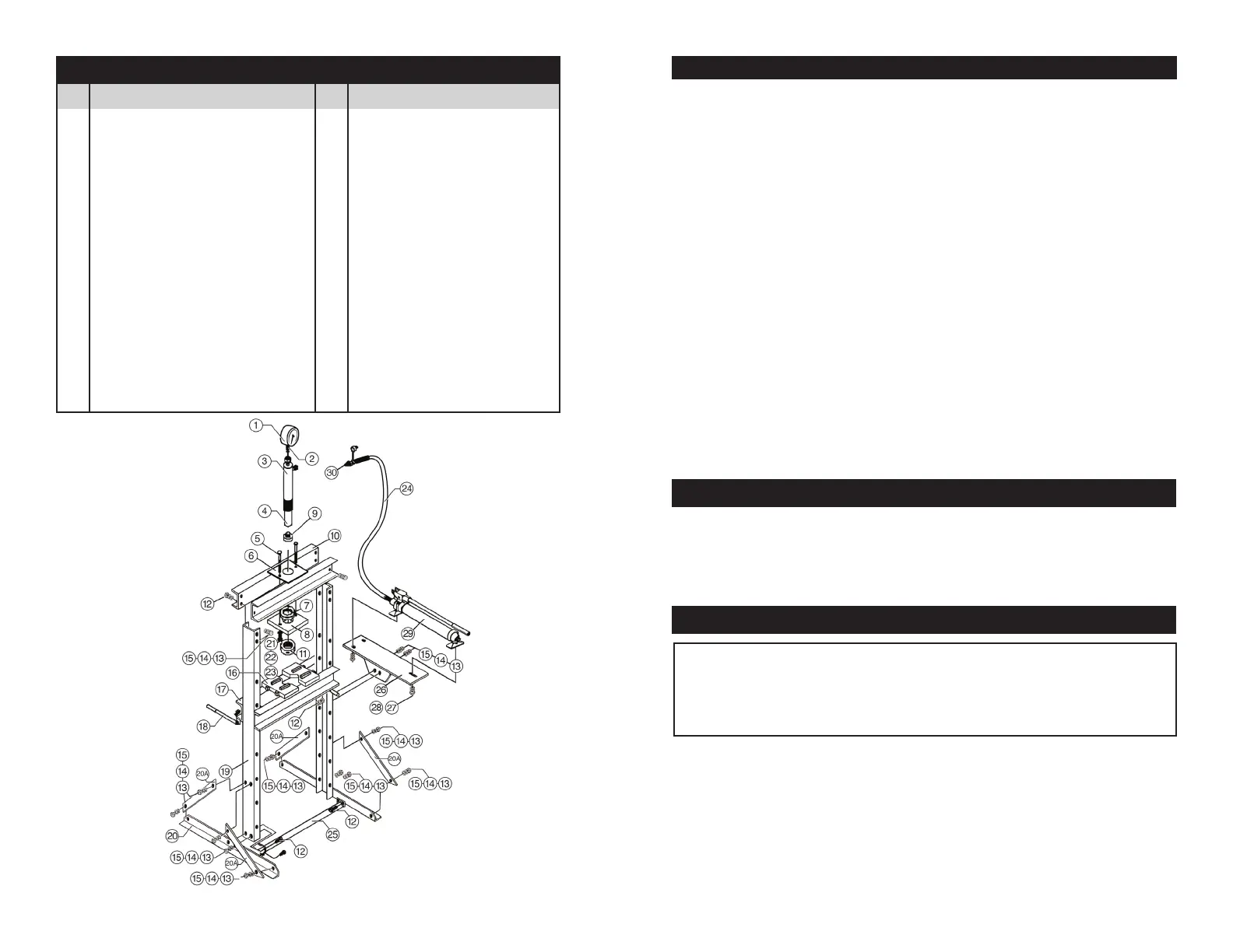
ASSEMBLY INSTRUCTIONS
1. Attach one base section to left post, add the support straps to the base and post
Do this using the bolts, washers, lock washers and nuts. Attach the other base
section and straps to the right post.
2. Put the press frame in an upright position, attach the two upper cross beams to
left and right posts using bolts washers, lock washers and nuts.
3. Put the upper plate onto the upper crossbeam, insert the bolt into the hole in the
upper plate, insert the ram into the hole in the upper plate.
4. Screw the upper round nut onto the ram until snug, put the under plate onto the ram
and secure the upper plate and under plate by tightening washers and nuts to bolts.
Screw the under round nut onto the ram and secure with a punch and soft face mallet.
5. Insert bed frame pin into the holes in the posts, then insert the press bed frame
into press frame and onto bed frame pin.
6. Attach the setting plate to the right post using bolts, washers, lock washers and nuts,
then secure the pump assemblies using the bolt and washers, and then insert the
handle to the handle bracket.
7. Connect the hydraulic hose fitting to the connection nut and assemble the
pressure connection nut and assemble the pressure gauge on the pressure
gauge connection nut which is on the top of ram.
8. Tighten all bolts and screws.
Use the exploded drawing as your guide to assemble. Lay all parts and
assemblies out in front of you before beginning. The following procedure
is recommended:
No. Description Qty.
1. Pressure gauge...................1
2. Nylon ring............................1
3. Ram assy.............................1
4. Screw M6............................1
5. Bolt M10............................. 2
6. Upper plate.........................1
7. Upper round nut................. 1
8. Under plate.........................1
9. Saddle.................................1
10. Upper cross beam..............2
11. Under round nut..................1
12. Bolt M12 X 30.....................14
13. Washer 12..........................22
14. Lock washer 12 Ø..............22
15. Nuts M12........................... 22
16. Pressure plate.....................2
No. Description Qty.
17. Bed frame.........................1
18. Bed frame pin.................. 2
19. Frame post......................2
20. Base plate........................2
20
A Support strap...................4
21. Washer Ø10.....................10
22 Lock washer Ø10............10
23. Nut M10..........................10
24. Hose................................1
25. Lower cross member.......1
26. Pump bracket..................1
27. Washer Ø8.......................3
28. Bolt M8 X 16....................3
29. Pump assy.......................1
30. Hose tting......................1
EXPANDED PARTS LIST
3
 Loading...