Position information (required for accurate time capture) is automatically
acquired by the unit, or can be manually entered through the set up
controls.
The local oscillator fitted can be a TCXO, OCXO or Rubidium. The
oscillator is locked to the GPS 1PPS signal by means of a phase locked
loop and provides a good quality 10MHz sine wave output, buffered
through an RF buffer, to give a standard 1V rms, 13 dBm, 50 ohm output
impedance RF signal onto a BNC output connector.
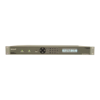
GPS status and health is internally monitored and reported on front panel
LED’s (power, lock, and fault LED indicators). Ethernet and RS232
monitor/control i/o ports also report antenna fault status. In addition the
unit provides a “holdover” clean contact closure on a rear panel
connector.
The FPGA provides a number of additional internally generated functions
including digital i/o capability (E1/T1 telecom, RS485, additional RS232,
event timer, programmable pulse rate) which are optionally made
available on the unit rear panel if required.
Due to the flexibility provided by the FPGA architecture, and available
built in i/o buffers, ptf is able to implement special i/o functions upon
request. If ordered with this unit, details of any special i/o functions, if any,
will be found in the appendix to this manual.
Standard unit set-up, monitoring and control is via either the RS 232 (DB9
connector) or Ethernet (RJ 45 connector) interfaces, which allow access
utilizing http, or telnet protocols. SNMP is optionally available.
Standard unit output functionality includes:
12 Channel GPS engine to provide internal time and frequency
reference information, including range autonomous integrity
monitoring (RAIM).
10MHz, 1V rms RF sine wave output into 50 ohms
1 PPS ttl output
IRIG B (AM) output
 Loading...