QT20 Power Supply Instruction Manual
Technical Data
QT20.241 QT20.361 QT20.481
Output Voltage DC 24-28V DC 36-42V DC 48-55V externally adjustable
Factory Set typ. 24.1V 36.0V 48.0V at full rated load
Output Current min 20-17.5A 13.3-11.4A 10-8.7A continuous
min 30-26A 20-17.1A 15-13A for typ. 4 sec
Output Power min. 480W 480W 480W continuous
min. 720W 720W 720W for typ. 4 sec
Output Ripple max. 100mVpp 150mVpp 100mVpp BW DC to 20MHz
Over-voltage Protection max. 35Vdc 53Vdc 60Vdc
AC Input Voltage - 3AC 380-480V -15/+15%, 50-60Hz TN, TT and IT mains
AC Input Current max. 0.9-0.65A / Phase at 3x 380 - 480Vac
Power Factor typ. 0.94 at 3x 380 - 480Vac
AC Inrush Current max. 4A peak, 1A
2
s at 3x 380 - 480Vac
Efficiency typ. 95.0 / 94.8% 94.8 / 94.6% 95.4 / 95.0% at 3x 400 / 480Vac
Losses typ. 25.3 / 26.4W 26.3 / 27.4W 23.1 / 25.3W at 3x 400 / 480Vac
Hold-up Time typ. 22ms at 3x 380 - 480Vac
Capacitive Loads - No limitations
Inductive Loads - No limitations
Limited Warranty - 3 year
Environment
Protection
Operational temperature -25 to +70°C De-rate above +60°C Output Overload, no-load, short-circuit proof
Storage temperature -40 to +85° C Storage, transport Degree of protection IP 20 EN/IEC 60529
Humidity 5 to 95% RH No condensation allowed Class of protection I PE (Ground) connection required!
Vibration sinusoidal 2g IEC 60068-2-6 Degree of pollution 2 EN 50178, not conductive
Shock 30g 6ms, 20g 11ms IEC 60068-2-27 Over-temperature protection yes Output shut-down with automatic restart
Output over-voltage protection yes Output shut-down with automatic restart
Over-voltage category III EN 50178
Penetration protection >3.5mm e.g. screws, small parts …
Phase failures or missing phases yes Device also operates with two phases
See specification on next page.
Internal input fuse Not included
Allowed output current versus
the ambient temperature
Ambient temperature is defined
2cm below the unit.
0%
25%
50%
75%
100%
125%
150%
-40°C -20°C 0°C 20°C 40°C 60°C 80°C
Ambient Temperature
for ty p. 4s
continuous
External protection External branch circuit protection is required to protect
the device. Use three thermo-magnetic circuit breakers
with a value between 3A and 16A. Choose tripping
characteristic B (US: F) or C (US: G).
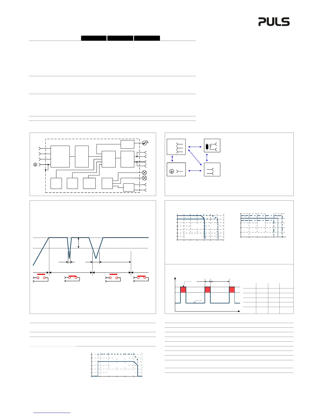
Functional Diagram
Dielectric Strength
Type tests and factory tests:
Conducted by the manufacturer.
Do not repeat test in field!
Field test rules:
(1) Use appropriate test equipment which
apply the voltage with a slow ramp!
(2) Connect L1, L2 and L3 together as well as all
output poles.
(3) Use only AC test-voltages with 50/60Hz.
The output voltage is floating and has no ohmic
reference to ground.
A
D
C
B
B
L1
Input DC-ok
Earth
Output
-
+
L3
L2
A B C D
Type Test 60s 2500Vac 3000Vac 500Vac 500Vac
Factory Test 5s 2500Vac 2500Vac 500Vac 500Vac
+
+
-
-
V
OUT
DC
ok
Output
Over-
Voltage
Protection
PFC
Converter
Input Filter
Input Rectifier
Inrush Limiter
Transient Filter
Output
Voltage
Regulator
Power
Converter
Output
Filter
DC ok
Relay
Output
Voltage
Monitor
Output
Power
Manager
Temper-
ature
Shut-
down
Over-
load
DC
ok
L2
L3
L1
Field Test 5s 2000Vac 2000Vac 500Vac 500Vac
Overload Performance
The unit is designed to support loads with a higher short-term
power requirement without damage or shutdown.
0V
4V
8V
12V
16V
20V
24V
28V
0A 5A 10A 15A 20A 25A 30A 35A
continuous for 4s
Output Current
0 s
1 s
2 s
3 s
4 s
5 s
110% 120% 130% 140% 150% 160%
Output Current
min.
max .
Output characteristic (typ.)
Curve is valid for the 24V unit. Units with output
voltages other than 24V have an equivalent and
proportional performance.
Bonus time
Duration until the output starts dipping.
Bonus Time is hardware controlled.
Repetitive pulse loading: Multiple pulses can be supported as long as the average (R.M.S.)
output current stays below the specified continuous output current.
Examples for pulse load
compatibility:
P
PEAK
P
0
T
PEAK
T
0
720W 480W 1s >25s
720W 0W 1s >1.3s
720W 240W 0.1s >0.16s
720W 240W 1s >1.6s
DC-ok Relay Contact
This feature monitors the output voltage, which is produced by the power supply, and is
independent of a return voltage from a unit which is connected in parallel.
Contact closes as soon as the output voltage reaches the nominal value.
Contact opens as soon as the output voltage dips more than 10%.
Short dips will be extended to a length of 250ms on the relay.
Dips shorter than 1ms will be ignored.
Contact ratings 60Vdc 0.3A, 30Vdc 1A, 30Vac 0.5A, resistive load
250ms
90%
V
ADJ
V
ADJ
closed
open
> 1ms< 1ms
10%
open
closed
V
OUT
Please note:
The DC-ok feature requires that the output voltage reach the nominal (=adjusted) level after
turn-on in order to function to specification. If this level cannot be achieved, the unit will show
an overload condition. The overload signal will disappear as soon as the adjusted voltage is
reached. This is an important to condition to consider particularly, if the load is a battery or
the power supply is used for N+1 redundant systems.
t
100%
P
PEAK
0%
T
PEAK
P
0
T
0
P
OUT
max.
150%
t
720W 240W 3s >4.9s
 Loading...