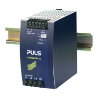
QT20 Power Supply Instruction Manual
Safety
Separation of output SELV IEC/EN 60950-1
EMC
The device is suitable for applications in industrial environment as well as in residential,
commercial and light industry environment without any restrictions.
For further details see datasheet.
PELV EN 60204-1, EN 50178, IEC 60364-4-41
EMC Immunity EN 61000-6-1, EN 61000-6-2 Touch current max. 0.7mA Earth leakages current, TN- mains
Isolation resistance min. 5MOhm Input to output, 500Vdc
EMC Emission EN 61000-3-2, EN 61000-3-3, EN 61000-6-3, EN 61000-6-4,
FCC Part 15 Class B
PE resistance max. 0.1Ohm Between housing and ground terminal
Transformer Safety transformer according to IEC/EN 61558-2-17 This device complies with FCC Part 15 rules. Operation is subjected to following two
conditions: (1) this device may not cause harmful interference, and (2) this device must
accept any interference received, including interference that may cause undesired operation.
Approvals See datasheet or markings on the unit
CE mark in conformance with EMC guideline 89/336/EEC and 93/68/EEC and low-voltage directive (LVD) 73/23/EWG.
Terminals and Connections
Terminals Input Output DC-ok
Type Bi-stable, quick-connect spring clamp terminals
Ferrules Allowed, but not required
Solid wire
0.5-6mm
2
0.5-6mm
2
0.5-6mm
2
Stranded wire
0.5-4mm
2
0.5-4mm
2
0.5-4mm
2
AWG AWG 20-10 AWG 20-10 AWG 20-10
Stripping length 10mm / 0.4inch
Pull-out force 10AWG:80N, 12AWG:60N, 14AWG:50N, 16AWG:40N (UL486E)
1. Insert the wire 2. Snap the lever
Use appropriate copper cables that are designed for an operating temperatures of 60°C (for ambient
up to 45°C) and 75°C (for ambient up to 60°C), minimum. Follow national installation codes and
regulations! Ensure that all strands of a stranded wire enter the terminal connection! Up to two
stranded wires with the same cross section are permitted in one connection point (except PE wire). Do
not use without PE (Ground) connection!
Physical Dimensions, Indicators and Cooling
Width 65mm / 2.56’’
Height 124mm / 4.88’’
Depth 127mm / 5.0’’ plus DIN-rail depth
Weight 870g / 1.92lb
DIN-Rail
Use DIN-rails according to EN 60715 or EN 50022
with a height of 7.5 or 15mm
Mounting
Orientation
Output terminal on top and input terminals on the bottom.
For other orientations see datasheet.
Indicators
DC-ok LED
(green)
Overload
lamp (red)
DC-ok
Relay
Normal operating mode ON OFF Closed
BonusPower
®
operation ON OFF Closed
Overload (V
OUT
< 90%) OFF ON Open
Short-circuit (V
OUT
= 0) OFF ON Open
Temperature shut-down OFF ON Open
No input power OFF OFF Open
Do not obstruct air flow! The unit is convection cooled. Ventilation grid must be kept free of any obstructions.
Keep installation clearances at higher ambient temperature and full load:
40mm on top, 20mm on the bottom, 5mm on the left and right side are recommended when loaded
permanently with full power. In case the adjacent device is a heat source, 15mm clearance are recommended.
PU-347.010.00-10B
Operation on Two Phases
DC
L1
L2
PE
L2
L1
L3
Fuse
L3
open
0%
25%
50%
75%
100%
-30°C -10°C 10°C 30°C 50°C 70°C
2AC 460 to 550V
2AC 340 to 460V
P
OUT
Parallel Operation
Power
Supply B
-
+
Load
+
-
Fuse
*)
Fuse
*)
AC
DC
AC
DC
-
+
Power
Supply A
(1) Use only power supplies from the same
Dimension Q-series.
(2) Adjust the output voltages of all power
supplies to approximately the same value
(±500mV). Otherwise, the DC-ok signal
might not work properly.
(3) A fuse (or diode) on the output is only
required if more than three units are
connected in parallel.
(4) Keep an installation clearance of 15mm
(left/right) between two power supplies and
avoid installing the power supplies on top of
each other.
(1) Operation on two phases is specified.
(2) Reduce output power according to curve. Exceeding the limits results in a thermal shut-down.
(3) The specification for EMC performance, hold-up time, losses and output ripple will no longer
be valid. Check suitability individually in the application.
Serial Operation
Power
Supply B
-
+
Load
+
-
AC
DC
AC
DC
-
+
Power
Supply A
Earth
(see notes)
(1) It is possible to connect as many units in
series as needed, providing the sum of the
output voltage does not exceed 150Vdc.
(2) Voltages with a potential above 60Vdc
are not SELV any more and can be
dangerous. Such voltages must be installed
with a protection against touching.
(3) For serial operation use power supplies
of the same type.
(4) Earthing of the output is required when
the sum of the output voltage is above
60Vdc.
(5) Keep an installation clearance of 15mm
(left/right) between two power supplies and
avoid installing the power supplies on top of
each other.
Check touch current (earth leakage current)! The total touch current is the sum of
the touch currents of all units. Safety limits – depending on the field of application -
apply for the allowed touch current!
open
close
Air flow

 Loading...