EN
PISA-B-812-B4 Installation Manual
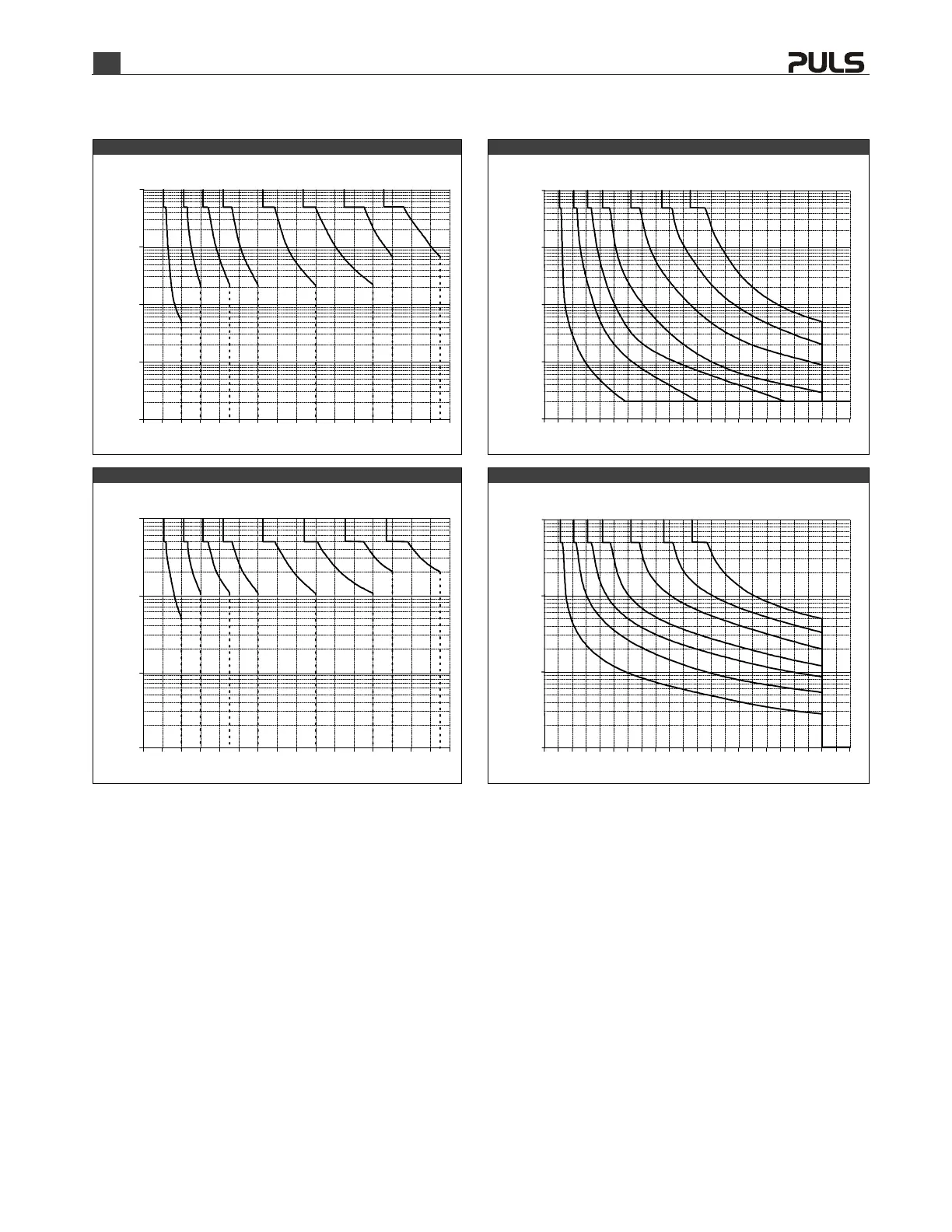
Tripping Diagrams
The following curves show the let-through current areas, which are located to the left of the curves, and the tripping areas, which are located to the right of the curves.
Channel 1 and 2 - Fast Characteristic Channel 3 to 8 - Fast Characteristic
Trip current setting
Output Current, typ.
10A6A4A3A2A1A 12A
0
100ms
1s
10s
10ms
2 4 6 8 10 12 14 16A
1ms
8A
Trip current setting
Output Current, typ.
10A6A4A3A2A1A
0
100ms
1s
10s
10ms
1ms
8A
2 4 6 8 10 12 14 16 22A18 20
Channel 1 and 2 - Slow Characteristic Channel 3 to 8 - Slow Characteristic
Trip current setting
Output Current, typ.
10A6A4A3A2A1A 12A
0
100ms
1s
10s
10ms
2 4 6 8 10 12 14 16A
8A
Trip current setting
Output Current, typ.
10A6A4A3A2A1A
0
100ms
1s
10s
10ms
8A
2 4 6 8 10 12 14 16 22A18 20

 Loading...