EasyManua.ls Logo

Puls PISA-B-812-B1 - User Manual

Puls PISA-B-812-B1
20 pages
Print Icon
To Next Page IconTo Next Page
Loading...
PISA-B-812-B1
PISA-B-812-B4
Apr. 2021 / Rev. 0.1 DS-PISA-B-812-Bx-xx-EN www.pulspower.com 1 / 20
All parameters are specified at 24Vdc input voltage, 8x5A output currents, 25°C ambient and after a 5 minutes run-in time unless otherwise noted.
ELECTRONIC FUSE
8X 24V, 2X 1-12A, 6X 1-10A
Eight Current Controlled Outputs
Adjustable Output Currents for Each Channel
Selective Tripping of Overloaded Channels
Compatible even with large Capacitive Loads
Output Currents Displayed Live on LED Matrix
Remote Reset or Reset via Pushbuttons
Common Signaling Relay Contact for Tripped
Channels (PISA-B-812-B1)
Digital Coded Signal Output for Tripped Channels
(PISA-B-812-B4)
Parameter Settings can be Locked by PIN-Code
ON/OFF Feature for Each Individual Output
Easy Wiring - Distribution Terminals for Negative Pole
3 Year Warranty
GENERAL DESCRIPTION SHORT-FORM DATA
The PISA-B devices are DIN rail mountable
eight channel protection modules with integrated
electronic fuses for 24V systems. They distribute the
current of a large power source to eight output
channels each of lower current and therefore allowing
for smaller wires to be used.
The output current of each channel can be set
individually. Channel 1 and 2 are optimized for loads
with large input capacitances. Connect such loads to
these channels to avoid false tripping or unexpected
switch-off such loads.
The PISA-B-812-B1 is equipped with a common
tripping signaling relay contact that reports tripped
channels, while the PISA-B-812-B4 has a digital coded
signal output built in for this function.
All PISA-B devices are equipped with push-in
terminals, which are optimized for automated wiring.
The mechanically robust housing is made of a high-
grade, reinforced molded material on the front and
of an aluminum body, which permits surrounding
temperatures up to +70°C.
Input voltage DC 24V -20%/+25%
Required input voltage
for turning-on of outputs
19.6Vdc
Input current 40A
Internal consumption 40mA PISA-B-812-B1
35mA PISA-B-812-B4
Adjustable
1/2/3/4/6/8/10/12A CH1 and CH2
Nominal output current
1/2/3/4/6/8/10A CH3 to CH8
40A Below +60°C ambientSum current all channels
30A At +70°C ambient
Derate between +60°C and +70°C
Current limitation
CH1-CH2 200% For 1A setting
150% For 2 - 8A settings
130% For 10 - 12A settings
CH3-CH8 50A
Tripping characteristics Slow or Fast Selectable
Tripping delay
CH1-CH2 2ms – 2s At short circuit
CH3-CH8 <10ms At short circuit
CH1-CH8 1.1s For slow tripping at 1.5x
nominal current
CH1-CH8 0.22s For fast tripping at 1.5x
nominal current
Max load capacitance capability
CH1-CH2 100mF Per channel
CH3-CH8 20mF Per channel
Voltage drop per channel
CH1-CH2 125mV For 10A load
CH3-CH8 165mV For 10A load
Standby losses 1W
Power losses 10.8W At 8x 5A load
Temperature range -25°C to 70°C
Size (w x h x d) 52x124x130mm Without DIN rail
Weight 370g / 0.82lb
ORDER NUMBERS MAIN APPROVALS
Description: Electronic Fuse PISA-B-812-Bx-xx
Order Number:
PISA-B-812-B1 Common signaling relay contact
PISA-B-812-B4 Digital coded signal output
Accessories:
BUS-BAR1-L102: A set for 2 modules
BUS-BAR1-L155: A set for 3 modules
BUS-BAR1-L500: Single piece L=500mm
For details and a complete approval list, see chapter 20.
UL 2367 UL 61010-2-201 IEC 61010
IEC 62368 planned
Question and Answer IconNeed help?

Do you have a question about the Puls PISA-B-812-B1 and is the answer not in the manual?

Puls PISA-B-812-B1 Specifications

General IconGeneral
Output Voltage24 VDC
Operating Temperature-25°C to +70°C
Dimensions124 x 124 x 117mm
Efficiency94.7%
ProtectionOverload, Short-circuit, Overvoltage
CertificationsUL, CE
Output Current20 A
Power Boost150% for 5 seconds

Summary

Intended Use

Installation Instructions

Safety Warnings and Guidance

Provides critical safety warnings and step-by-step guidance for safe and correct installation of the device.

Typical Wiring Scheme

Wiring Diagrams

Illustrates various methods for connecting the fuse module to loads and power supplies using diagrams.

DC-Input

Power Input Requirements

Details the requirements and specifications for the DC power input, including voltage range and polarity.

Output

Channel Characteristics

Explains the output characteristics, load capabilities, and turn-on sequence for the device's eight channels.

Output Tripping Characteristics

Tripping Behavior and Diagrams

Describes the tripping behavior, delay settings, and provides tripping diagrams for different channels.

Control And Monitoring Features

Measurement Mode

Explains the measurement mode, LED indicators for actual current, and channel status.

Parameter Mode

Details the parameter mode for setting trip currents, characteristics, and PIN protection.

Changing Trip Currents and Characteristic

Describes how to adjust trip currents and select tripping characteristics, including PIN locking.

Digital Coded Interface (PISA-B-812-B4)

Digital Alarm Signal Output

Describes the digital coded alarm signal output for channel tripping information.

Alarm Relay Contact (PISA-B-812-B1)

Alarm Signal Relay

Details the alarm relay contact, its ratings, and conditions for activation.

Reset Input

Channel Restart Functionality

Explains how to restart switched-off channels using the reset input or control button.

Efficiency And Power Losses

Performance Metrics

Presents data on the device's efficiency and power consumption under various load conditions.

Functional Diagram

Internal Structure

Provides block diagrams illustrating the internal functional structure of both PISA-B-812-B1 and B4 models.

Front Side And User Elements

Front Panel Components

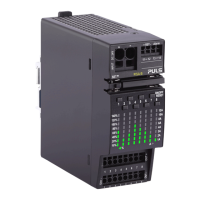
Identifies and explains the components and labels on the front panel of the device.

Terminals And Wiring

Connection Specifications

Details the types of terminals, wire compatibility, stripping lengths, and required tools for connection.

Lifetime Expectancy

Service Life Estimation

Provides estimated service life based on electrolytic capacitor lifetime, with caveats.

MTBF

Failure Rate Analysis

Explains Mean Time Between Failure calculations and lists MTBF values for different conditions.

EMC

Electromagnetic Compatibility

Covers Electromagnetic Compatibility (EMC) immunity, emissions, and performance criteria according to standards.

Environment

Operating Conditions

Specifies operational and storage temperatures, humidity, altitude, and vibration/shock resistance.

Safety Features And Protection Features

Protective Measures

Lists safety features like isolation resistance, over-voltage, and temperature protection, and input polarity protection.

Approvals And Fulfilled Standards

Certifications and Compliance

Lists certifications, standards compliance (IEC, UL, VDMA), and approval reports for the device.

Regulatory Compliance

EU Directives Conformance

Outlines compliance with EU directives like EMC, REACH, WEEE, and RoHS.

Physical Dimensions And Weight

Device Size and Mass

Provides detailed dimensions (width, height, depth), weight, and DIN rail mounting specifications.

Accessories

POWER CONNECTION - POWER-BUS-BARS

Details power-bus-bars for electrical connection of PISA-B modules, including types and specifications.

Related product manuals