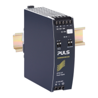
QS3.241
Q-Series
24V, 3.4A, SINGLE PHASE INPUT
Jul. 2020 / Rev. 2.3 DS-QS3.241-EN
All parameters are specified at 24V, 3.4A, 230Vac, 25°C ambient and after a 5 minutes run-in time unless otherwise noted.
www.pulspower.com Phone +49 89 9278 0 Germany
6/26
UTPUT
tage nom. 24V
ange 24-28V guaranteed
max. 30V
***)
at clockwise end position of potentiometer
typ. 24.1V ±0.2%, at full load, cold unit
max. 10mV 60-300Vac
max. 100mV static value, 0A 3.4A
ltage max. 50mVpp 20Hz to 20MHz, 50Ohm
nom. 3.4A continuously available at 24V, see Fig. 6-1
continuously available at 28V, see Fig. 6-1
nom. 5A
*)
short term available BonusPower
® *)
,
at 24V, for typical 4s, see Fig. 6-1
nom. 4.5A
*)
short term available BonusPower
® *)
,
at 28V, for typical 4s, see Fig. 6-1
utput power nom. 80W / 84W continuously available at 24V / 28V
nom. 120W / 126W
*)
short term available BonusPower
® *)
at 24V / 28V
®
time typ. 4s duration until the output voltage dips, see Fig. 6-2
min. 3s
max. 5s
®
recovery time typ. 7s overload free time to reset power manager, see Fig. 6-3
cont. current
-circuit current min. 3.5A
**)
continuous, load impedance 25mOhm, see Fig. 6-1
max. 4.2A
**)
continuous, load impedance 25mOhm, see Fig. 6-1
min. 5.2A
**)
during BonusPower
® *)
, load impedance 25mOhm
max. 6.0A
**)
during BonusPower
® *)
, load impedance 25mOhm
max. 6.0A
**)
continuous, load impedance <10mOhm, see Fig. 6-1
included inside the power supply
*) BonusPower®, short term power capability (up to typ. 4s)
The power supply is designed to support loads with a higher short-term power requirement without damage or shutdown. The short-
term duration is hardware controlled by an output power manager. This BonusPower
®
is repeatedly available. Detailed information
can be found in chapter 23.1. If the power supply is loaded longer with the BonusPower
®
than shown in the Bonus-time diagram (see
Fig. 6-2), the max. output power is automatically reduced to 80/84W.
**) Discharge current of output capacitors is not included.
***) This is the maximum output voltage which can occur at the clockwise end position of the potentiometer due to tolerances. It is not
guaranteed value which can be achieved. The typical value is about 28.6V.
Peak current capability (up to several milliseconds)
The power supply can deliver a peak current which is higher than the specified short term current. This helps to start
current demanding loads or to safely operate subsequent circuit breakers.
The extra current is supplied by the output capacitors inside the power supply. During this event, the capacitors will be
discharged and causes a voltage dip on the output. Detailed curves can be found in chapter 23.2.
Peak current voltage dips
typ. from 24V to 18.5V at 6.8A for 50ms, resistive load
typ. from 24V to 12V at 13.5A for 2ms, resistive load
at 13.5A for 5ms, resistive load
 Loading...