Standard Checking Procedure
Dealer Development Center
30
Dealer Development Center
29
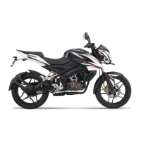
Rear Brake Light Switch Adjustment
When either the front or rear brake is applied, the brake light glows on.
The front brake light switch requires no adjustment but the rear brake light
switch should be adjusted in accordance with the periodic maintenance
chart.
Inspection :
• Turn on the ignition switch. The brake light should go on wheel the front
brake is applied.
• If it does not, then inspect the front brake light switch.
• Check the operation of the rear brake light switch by depressing the
brake pedal. The brake light should glow after about 15 mm of pedal
travel.
• If it does not, adjust the rear brake light switch.
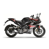
Adjustment :
• Adjust the rear brake light switch (A) by rotating the switch nut to create
adequate tension in spring to operate the switch.
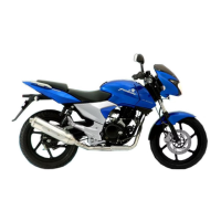
Rear Brake Pedal Position Adjustment
To suit rider foot comfort / operating style the angle of the rear
brake pedal can be adjusted by loosening the lock nut (A) and
adjusting the bolt (B).
Ensure free play by turning the adjuster clockwise or anticlockwise to
achieve specified free play. Fix the rubber sleeve on the bolt.
Note : After pedal position adjustment, it is necessary to set the free play.
Front Brake Free Play Adjustment
There is no need for free play adjustment, since the pistons in
caliper assembly will move towards the pads and take new positions
in order to automatically compensate for pad wear. The free play will
be approximately 2 ~ 3 mm.
Front Brake Lever Play : 2 ~ 3 mm.
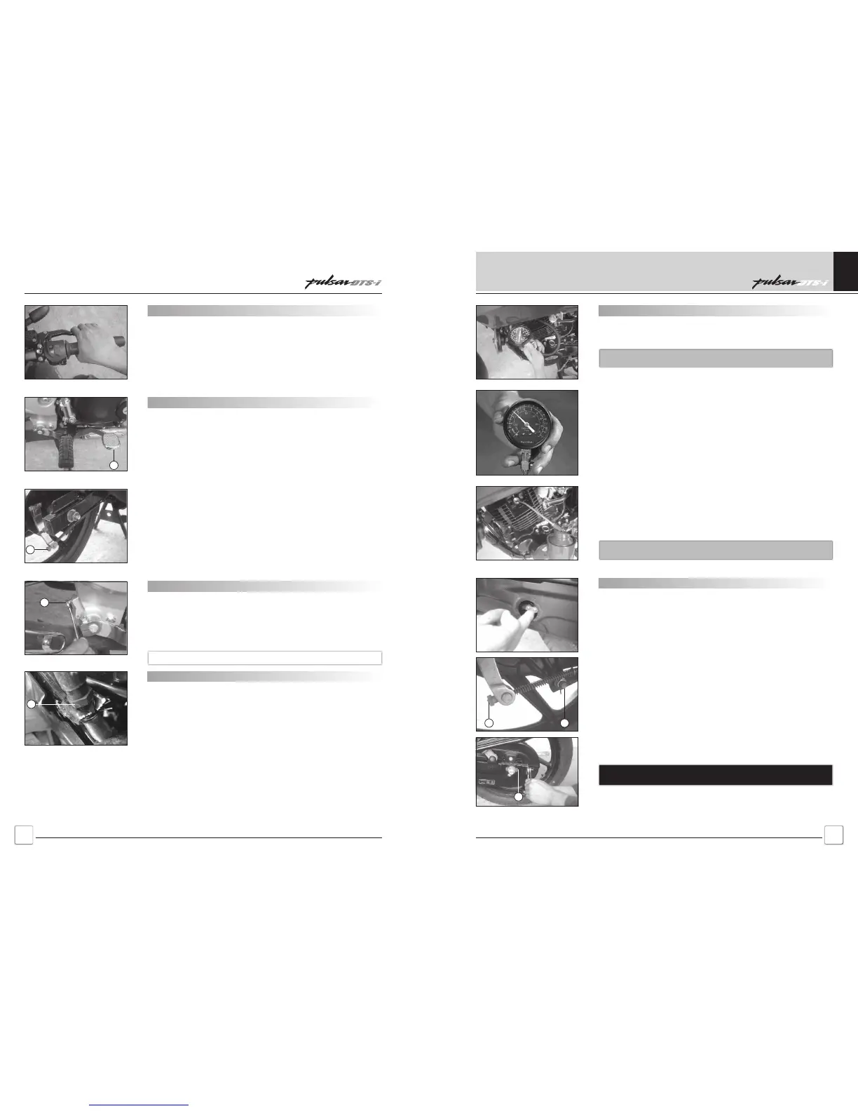
Rear Brake Pedal Adjustment
Check the rear brake pedal play as stated below. If it is more or
less than the standard, adjust the rear brake.
• Depress the rear brake pedal lightly by hand. This is free play.
• If the rear brake pedal free play is incorrect, adjusting the rear
brake shoe adjuster nut (A).
• Operate the pedal (B) for few times to see that it returns to its
rest position immediately upon release.
• Rotate rear wheels to check for brake drag.
• Check braking effectiveness.
• If there is any doubt as to the conditions of the brake, check the
brake parts for wear or damage.
• Turn the adjuster until the rear brake pedal have the correct
amount of play.
Rear Brake Pedal Play : 25 ~ 30 mm.
B
A
B
A
Pulsar DTS-i UG-III-180cc Training NotesPulsar DTS-i UG-III-180cc Training Notes
Compression Pressure Testing
For testing the compression pressure first warm up the engine.
Remove the spark plug. LH side.
Caution : Disconnect H. T. lead cable from second spark plug i.e. RH
side.
Fit the compression gauge with adapter in the Spark plug hole.
Open the throttle fully – then kick 5 times instantaneously.
Note the reading in the compression gauge.
Release the pressure by pressing the release valve on hose pipe.
Take average of 3 such readings for noting actual compression
pressure.
2
Confirm the compression pressure is between 6 to 10 Kg/cm
Wet Compression Test :
If the compression pressure is found below lower limit than
specified, put few drops of engine oil through the spark plug hole
and again check compression pressure.
If you find considerable increase this time, then cause for the low
compression pressure lies in Cylinder / Piston assembly.
If compression pressure remains the same, then the cause for low
compression pressure lies in Cylinder / Head assembly.
Caution : If wet compression is done, remove second spark plug and
clean thoroughly to avoid oil fouling before fitment.
Chain Slack Adjustment :
• Set the motorcycle upon its centre stand.
• Rotate the rear wheel to find the position where the chain is
tightest and measure the vertical movement midway between the
sprockets.
• If the drive chain is too tight or too loose, adjust it so that the
chain slack will be within the standard value i.e. 25-30 mm.
• Loosen the rear torque link nut (A) & rear brake adjusting nut (F).
• Loosen the left and right chain adjuster lock nuts (B).
• Loosen the axle nut (C).
• Loosen the bearing carrier nut (D).
• If the chain is too tight, back out the left & right chain adjusting
nuts evenly & kick the wheel forward until the chain is too loose.
• Turn both chain adjusting nuts evenly until the drive chain has the
correct amount of slack. To keep the chain and wheel properly
aligned, the notch (E) on the left chain adjuster should align with
the same swing arm mark that the right chain adjuster notch (E)
aligns with.
Warning : Misalignment of the wheel will result in abnormal wear, and
may result in unsafe riding condition.
AF
E
Schedule Maintenance
 Loading...