Dealer Development Center
28
Dealer Development Center
27
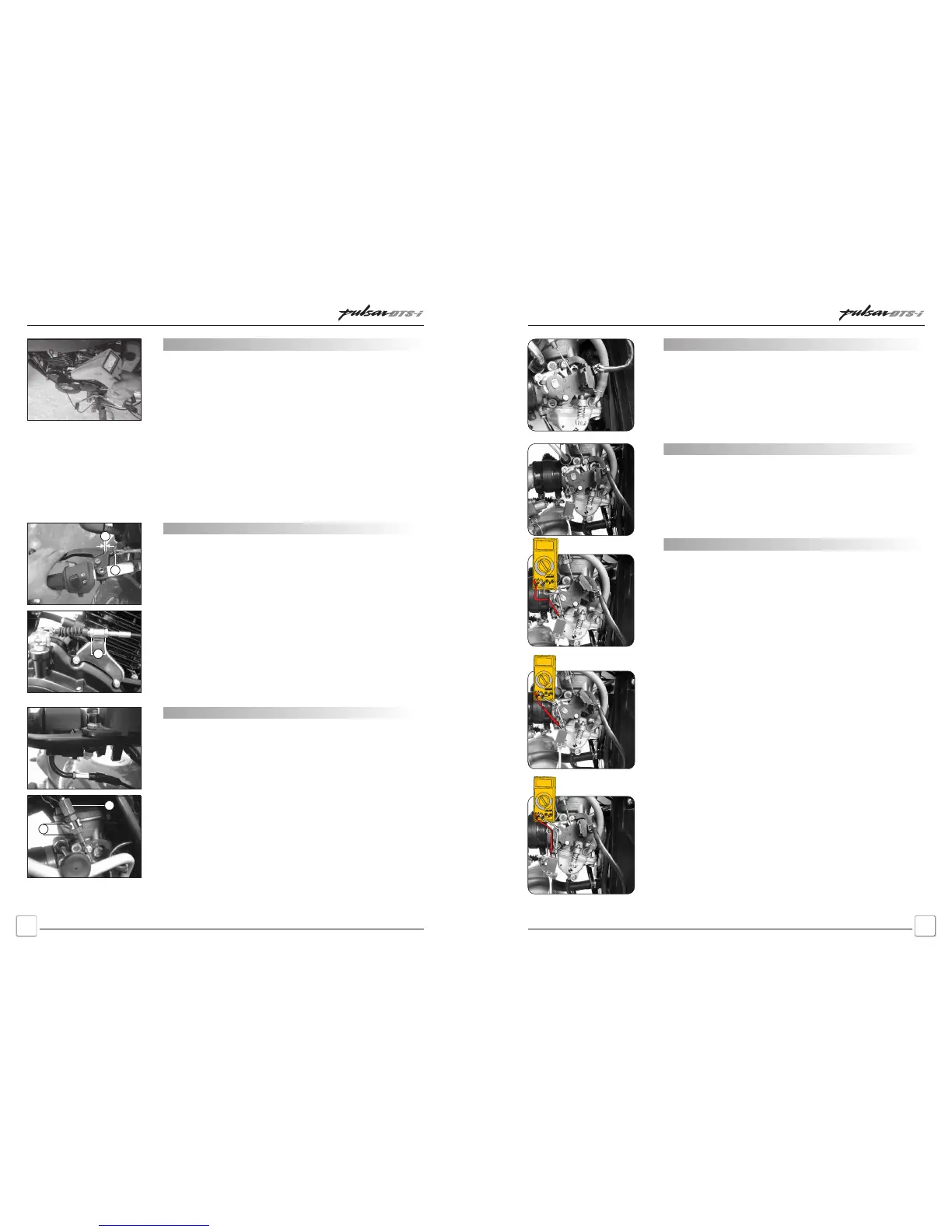
Ignition Timing Inspection
Connect cable of stroboscope to one of the H. T. Coil carrying
current to spark plug.
Start the engine.
Aim the stroboscope light at Magneto cover glass window.
¡ At idling speed the ‘F’ marked line on the rotor coincide with
0
the line mark on magneto side c’case. (10 BTDC @ 1500 rpm).
¡ As the engine rpm is increased the ‘A’ marked on the rotor
0
coincide with the line mark on magneto side c’case. (28 BTDC
@ 3500 rpm).
¡ This indicates the advance timing is functioning correctly.
¡ Remember the ‘T’ marked line is a reference line for TDC
position of the piston and is not for Ignition timing.
Clutch Lever Free Play Adjustment
• Slide the dust cover at lever yoke end.
• Check that the clutch cable outer end is fully seated in the
adjuster.
• Turn the adjuster (A) until the proper amount of free play can be
obtained.
• Tighten the lock nut (B) against the adjuster. If the clutch free play
cannot be adjusted with the adjuster at the handle bar end, use
the adjuster at the lower ends of the clutch cable situated on
clutch cover.
• Loosen the 2 lock nuts (C) on clutch cable bracket and adjust
threading in the adjuster provided on the clutch cover. Tighten
both the lock nuts on clutch cable bracket by holding one nut and
tightening the other, after the required free play.
Clutch Lever Free Play : 2 ~ 3 mm
Accelerator Free Play Adjustment
• Turn the adjuster (A) until the proper amount of free play can be
obtained.
• Tighten the lock nut (B) against the adjuster.
• If the accelerator free play can not be adjusted with the adjuster
at the handle bar end, use the adjuster at the lower ends of the
Accelerator cable situated on carburettor.
• Loosen the 2 lock nuts (C) on accelerator cable bracket end
adjust by adjuster (D) provided on the cable.
• Tighten both the lock nuts on bracket by holding one nut and
tightening the other, after ensuring the required free play.
Accelerator Grip Free Play : 2 ~ 3 mm
B
A
C
D
C
Pulsar DTS-i UG-III-180cc Training NotesPulsar DTS-i UG-III-180cc Training Notes
Reed Switch Setting and Checking
Check throttle lever movement by rotating it with hand. It should not
be sticky in operation and should return back it self on releasing.
bracket Multimeter should show continuity.
• Magnet should not touch with reed switch.
• Gap between Magnet & Reed Switch should not be more than 2.5mm.
• Movement of throttle lever with magnet assembly and Reed Switch
fitted should be free.
Reed Switch : Setting
• Accelerator cable play: 2-3 mm by adjusting the Adjuster
• Protude stopper of the throttle lever bracket must on idling screw tip.
Reed Switch : Checking
• Keep throttle at zero position.
• On connecting multimeter to Reed Switch coupler it should show
continuity.
• When throttle is open and Reed Switch magnet crosses to straight
edge of fix bracket of Reed Switch multimeter should show
discontinuity.
• On De-acceleration, when of Reed Switch magnet re-coinsides with
straight edge of fix bracket of Reed Switch Multimeter should show
continuity.
Gap
2.5mm max.
.
0
0
0
1
0
.
0
0
Schedule MaintenanceSchedule Maintenance
 Loading...