Dealer Development Center
26
Dealer Development Center
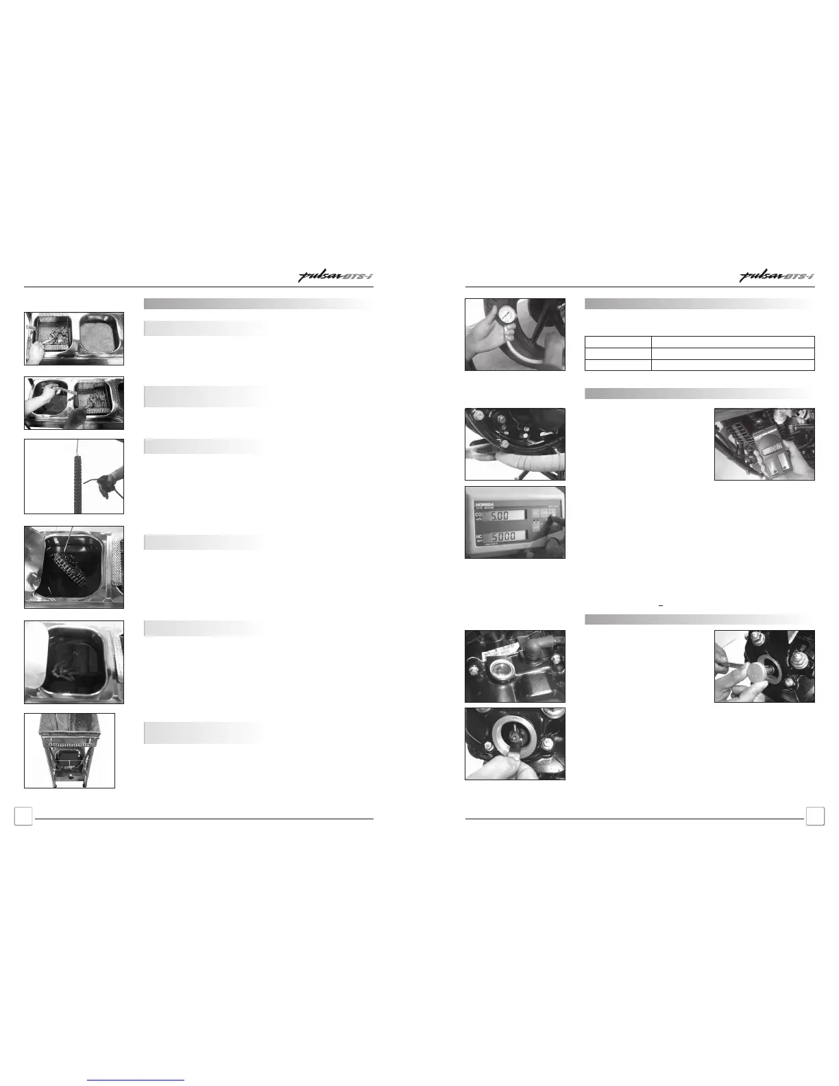
25
3rd Stage:
Dip into SAE 90 Oil
1st Stage:
Clean with Kerosene
Blow Compressed Air
Soak into SAE 90 Oil
Final Stage:
Hook Chain for
dripping of excess oil
2nd Stage:
Clean with Cleaner
Kerosene again
Drive Chain Cleaning / Lubrication
Pulsar DTS-i UG-III-180cc Training NotesPulsar DTS-i UG-III-180cc Training Notes
Tyre Air Pressure
• Keep appropriate tyre pressure as mentioned below to increase
life of this tyre and for better fuel consumption.
Front
Rear - with Solo
Rear - with Pillion
2
1.75 Kg/cm (25 PSI)
2
2.00 Kg/cm (28 PSI)
2
2.25 Kg/cm (32 PSI)
Important Adjustments and
Checking Procedures
Idling Speed Adjustment
Whenever the idling adjustment is
disturbed follow the procedure
given below for setting proper
engine idling.
• Start engine & drive it for at least
5 kms. or warm the engine till
0
the oil temp reaches 60 C.
Tappet Clearance Setting
• Ensure that the engine is cold.
• Ensure the ‘T’ mark on the
‘Rotor’ match with the mark on
the ‘Crankcase LH’. At this stage
the ‘Piston’ is at TDC and both
the ‘Tappets’ are free.
• Holding tappet screw firmly with
special tool loosen the tappet
• Remove the Bolt/Plug near Exhaus TEC
• Connect the probe of CO analyser. Set the CO between
1.75 ~ 2.25% by adjusting volume control screw.
• Then set the engine idling r.p.m. by rotating the idle adjustment
screw clockwise or anticlockwise by hand.
• For the precise adjustment of idling speed, use of tachometer is
recommended.
• Rotate the throttle a few times to make sure that the idling speed
does not change. Readjust if necessary.
• Do not attempt to compensate for faults in other systems by
adjusting the idle speed.
Idling Sped : 1400 + 100 rpm
screw nut.
• Put the feeler gauge, measure and adjust the clearance.
• Lock the nut holding screw with special tool after getting desired
clearance.
• Again check the tappet clearance with gauge. The gauge should
slide with slight resistance between tappet and valve stem head
feeler and tighten the check nut with a spanner.
• Inlet Valve : 0.05 mm • Exhaust Valve : 0.1 mm
Special Tools : Feeler Gauge - 69 7502 51
: Valve Adjusting Screw Holder - 37 1031 53
Schedule MaintenanceSchedule Maintenance
 Loading...