Dealer Development Center
52
Dealer Development Center
51
Pulsar DTS-i UG-III-180cc Training NotesPulsar DTS-i UG-III-180cc Training Notes
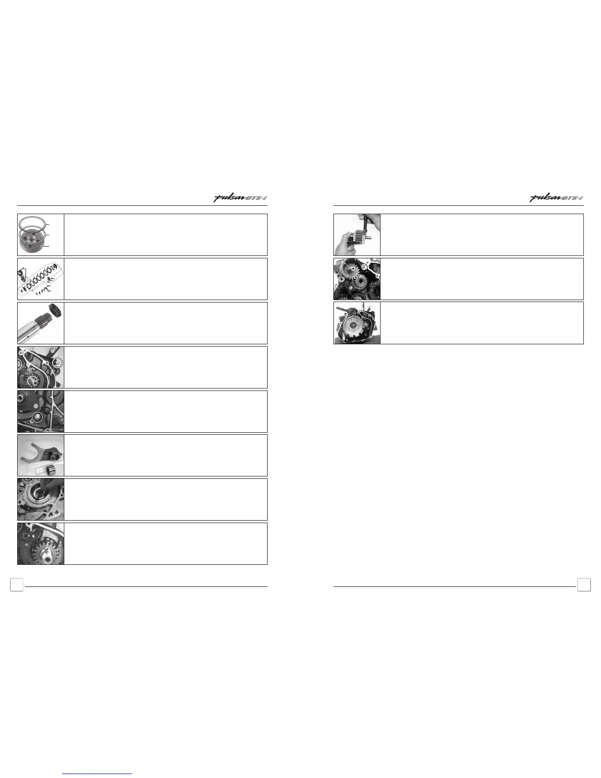
• Ensure damper rubber fitment on magneto side guide plate.
• When splitting crankcase always remove 1 long bolt fitted from clutch side
first.
• Remove long bolt immediately after removal of long bolt clutch side.
• Ensure proper fitment of bolt with copper washer to avoid oil leakage.
• Shifter fork is having a roller. These roller are one side tappered inner dia.
• Taper portion of roller should face towards fork gear shift.
• Input shaft has special nut.
• Thick spacer washer tapered I.D. it should be placed on tapped portion of
Input Shaft.
• Input Shaft has left hand threads.
• After placing Belleville, fit clutch plate with 48 friction material cubs (A) with
more I.D.
• 4 Nos. of clutch plates with 36 friction material cubs (B) alternatively along with
steel plates.
• Fit top clutch plate with 40 friction material cubs (C).
Ensure
• While assembling hub clutch place plain washer first and then place belleville
washer. Concave face should be upwards i.e. toward technician.
Belleville
Washer
Plain
Washer
Clutch
Hub
• Fit primary gear drive (A).
• The mark teeth of the primary gear should match with the line mark on the c’case.
This indicated that the piston is at TDC position. This procedure should be carried
before fitting the ‘Clutch Housing’ & this position should not be disturbed while
fitting the ‘Clutch Housing’.
2
14
17
1
16
9
8
12
10
5
7
6
7
6
7
6
4
6
15
11
13
3
• Load the assly balancer idler gear with 2 teeths from either side using the
special tool.
• Take the ‘Assembly Balancer Idler Gear’ along with Thrust Washer which is pre-
loaded and is held in special tool, Slide down the special tool with ‘Gear’ to engage
the bottom half of the ‘Assembly Balalncer Idler Gear’ with the ‘Body Balancer Gear
Assembly’
• Fit ‘Thrust washer’ on the other side.
• On assembly of ‘Assembly Balancer Idler Gear’ the itched/Dot mark of ;Body
Balancer Gear Assembly’ should match with the line mark on the ‘Crankcase’.
Holding the ‘Assembly Balancer Gear’ in special tool now slide inside the ‘Clutch
Housing’ so that the ‘Clutch Housing’ smoothly engages with the top half of
‘Assembly Balancer Idler Gear’.
• Remove the special tool gently.
• Fit 2 dowels and Assly Balancer Idler Gear Cover
• Ensure perfect marking of gear marks with respect to crankcase mark.
Important Points to RememberImportant Points to Remember
 Loading...