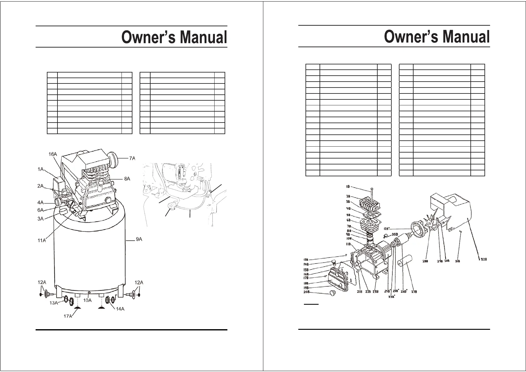
PARTS LIST A / ASSEMBLY DIAGRAM A
Part Description Qty.
1A ON/OFF Power Switch 1
2A Tool Pressure Adjuster 1
3A Tank Pressure Gauge 1
4A Tool Pressure Gauge 1
5A Pressure Release Valve 1
6A Air Flow Valve 1
7A Air Filter 1
8A Air Flow Lid 1
9A Air Tank 1
10A Water Drain Valve 1
Part Description Qty.
11A Quick Connect Coupler 1
12A Rubber Wheel with Bolt 2
13A Washer 2
14A Nut 2
15A
16A Oil Drain Plug with Gasket 1
17A Foot 2
18A Unloader Valve 1
19A Polyurethane Unloader Tube 1
20A Copper Air Tube 1
5A
18A
19A
20A
(Rear View with motor cover removed.)
9
NOTE: Some parts are listed and shown for illustration purposes only, and are not avail-
able individually as replacement parts.
PARTS LIST B / ASSEMBLY DIAGRAM B
Part Description Qty.
1B Bolt 4
2B Cylinder Case 1
3B Gasket 1
4B Valve Seat 1
5B Gasket 1
6B Cylinder 1
7B Compression Ring 2
8B Oil Scraping Ring 1
9B Piston 1
10B Gasket 1
11B Piston Pin 1
12B* End Cover 1
13B Crankshaft Retainer 2
14B Breather Valve 1
15B Connecting Rod 1
16B Gasket 1
17B Bolt 6
18B Front Cover 1
Part Description Qty.
19B Gasket 1
20B Oil Window 1
21B Crankshaft Bolt 1
22B Crankshaft 1
23B Crankshaft Case 1
24B* Stator 1
25B* Bearing 2
26B* Armature 1
27B Capacitor ,120uF±5% 1
28B Radiating Fan Wheel 1
29B Retainer Ring 1
30B Bolt 4
31B Screw 2
32B Radiating Cover 1
33B* Seal Washer 1
34B Motor Assembly 1
35B Overload Switch 1
*Not available individually. Must be ordered as entire Motor Assembly (See part #34B).