The provided document is a service instruction manual for a series of Pumpex electric submersible waste water pumps, specifically models K 82, K 85, K 101, K 102, K 104, K 151, and K 155.
Function Description
These pumps are designed for handling waste water and are available in various configurations to suit different installation and operational requirements. The core function involves pumping waste water, with specific models optimized for stationary, portable, or dry pit installations.
Pump Design: The pumps feature a design focused on high reliability and ease of maintenance. The number of major parts is kept to a minimum, and special tools are generally not required for disassembly and assembly.
Electric Driving Unit Components: The electric driving unit comprises several key components:
- Stator Unit: Includes the stator and stator housing.
- Rotor Unit: Consists of the rotor, shaft, and bearings.
- Impeller: The component responsible for moving the fluid.
- Oil Housing: Contains the oil for lubrication and cooling.
- Mechanical Shaft Seal Unit: Prevents fluid leakage along the shaft.
- Junction Box: Includes the junction box cover, terminal board, and cable entries.
An exchange system is utilized for the Stator Unit and Mechanical Shaft Seal Unit, indicating that these components can be easily replaced with rebuilt units.
Pump Designations and Usage Features:
-
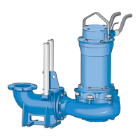
KP-F (Stationary Waste Water Pump with Channel Type Impeller):
- Operation: Designed to operate completely or partially submerged in the liquid.
- Connection: Automatically connects to a Discharge Connection fixed to the sump floor.
- Maintenance: Can be easily hoisted up along guide bars for inspection and service.
- Impeller Type: Channel type impeller, suitable for handling solids in waste water.
-
KL-V (Stationary Waste Water Pump with Vortex Impeller):
- Operation & Installation: Equivalent to KP-V in terms of operation and installation arrangement.
- Impeller Type: Vortex impeller, typically used for fluids with high solid content or fibrous materials, as it creates a vortex to move the fluid without direct contact with the impeller vanes.
-
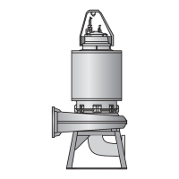
KP-T (Stationary Waste Water Pump with Channel Type Impeller for Dry Pit Installation):
- Installation: Designed for dry pit installation, meaning the pump itself is not submerged but the inlet is connected to the waste water source.
- Watertight Design: The driving unit has a watertight design to prevent damage in case of flooding.
- Inlet Connection: The inlet of the volute is drilled and tapped in accordance with metric flange standards.
- Impeller Type: Channel type impeller.
-
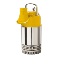
KE (Portable Waste Water Pump with Channel Type Impeller):
- Operation: Designed to operate completely or partially submerged.
- Connection: The volute is equipped with a hose connection.
- Stability: Includes a base stand for stability during portable use.
- Impeller Type: Channel type impeller.
Important Technical Specifications
The data plate information provides crucial technical specifications for the pumps:
- Type of Pump (A): Identifies the pump model (e.g., K 80).
- Serial Number (B): Unique identifier for each pump.
- Working Voltage (C) (U): The voltage at which the pump operates (e.g., 400 V Y).
- Rated Current (D) (I): The nominal current draw of the pump (e.g., 5.4 A).
- Rated Output (E) (P.2): The power output of the motor (e.g., 2.0 kW).
- Cos φ (F): Power factor.
- Frequency (G): The operating frequency of the motor (e.g., 50 Hz).
- Engine Speed (n): The rotational speed of the motor (e.g., 1385 rpm).
- Winding Class (Class F): Indicates the insulation class of the motor windings, determining the maximum permissible operating temperature.
- IP Rating (IP68): Ingress Protection rating, signifying that the pump is dust-tight and protected against continuous immersion in water.
- Weight (9): The total weight of the pump (e.g., 98 kg).
- Head (H): The maximum vertical distance the pump can lift water (e.g., 20 m).
Oil Capacity:
- K 82-104: 2.8 litres
- K 102-155: 4.8 litres
- Oil Type: Enerpar M002 or similar.
Maintenance Features
The manual details several maintenance procedures, emphasizing ease of service.
Disassembling:
- Driving Unit Separation: The driving unit is attached to the volute by two latch bolts. These can be loosened with a supplied wrench, allowing the driving unit to be separated from the volute.
Exchange of Oil:
- Procedure: Oil exchange is recommended if the oil is discoloured by water or during a complete overhaul. The driving unit is placed horizontally with the oil stick pointing down. The oil stick is loosened to relieve pressure, and an air plug on the opposite side is loosened to drain oil faster. New oil (Enerpar M002 or similar) is filled after draining.
- Gaskets: Gaskets for the oil stick and air plug should be checked for good condition.
Removal of Impeller:
- Procedure: The impeller is fitted on a cylindrical shaft end. A piece of wood or pipe can be used to prevent the impeller from rotating while loosening the impeller nut with a socket wrench (19 mm or 24 mm).
- Impeller Removal: The impeller has a light fit and uses a flat key; it can be removed using two large screwdrivers as pry bars.
Removal of Mechanical Shaft Seal Unit:
- Procedure: Three screws hold the seal unit to the oil housing bottom. The seal unit flange has threaded holes. After cleaning these holes, two M6 screws (approx. 40 mm long) can be fitted into them. Turning these screws evenly will back off the seal unit from the oil housing bottom.
- Replacement: Defective seal units should always be replaced, ideally by sending them to a service point for a rebuilt unit.
Removal of Stator Unit:
- Procedure: With the driving unit upright, screws holding the stator housing and oil housing together are removed. The stator unit can then be lifted away. Gentle tapping with a soft hammer may be needed if it doesn't separate easily.
Removal of Shaft/Rotor Unit and Bearings:
- Procedure: Three stop screws hold the shaft/rotor unit and oil housing together. Removing these screws allows the shaft/rotor unit to be pressed out.
- Bearing Replacement: Bearings that have been in contact with water or are damaged must be replaced. Bearings are removed using a standard bearing puller after cleaning and oiling the shaft.
Exchange of Stator Unit:
- Troubleshooting: If the motor overload protector trips repeatedly, the stator should be checked. This involves removing the junction box cover, disconnecting motor cable leads, and recording their colours and terminal board positions.
- Insulation Check: Stator insulation is checked with a 500 V megger. Reading should exceed 1 megohm between winding phases and between windings and ground. If below, the stator unit should be dried in an oven (preferably not exceeding 90°C).
- Thermal Contact Check: The three built-in thermal contacts are checked for continuity using an ohmmeter or bridge. If a circuit is open, the defective contact is identified and can be bypassed according to the wiring diagram.
- Replacement: If insulation remains low after drying, the stator unit (stator and stator housing) should be replaced with a rebuilt unit from a service point.
Disassembly of Cable Entry:
- Replacement: If water has entered the junction box via the cable entry, the cable entry bushings should be replaced. This involves removing the strain relief clamp, unscrewing the cable entry body, and pulling out the cable, rubber bushing, and washers.
Assembly Procedures (General):
- Cleaning: All parts, especially O-ring grooves and mating surfaces, must be carefully cleaned before assembly.
- Lubrication: O-rings should be greased or oiled to prevent damage during assembly. Screw threads should also be greased or oiled to simplify future disassembly.
Assembly of Cable Entry:
- Bushing Selection: The inner diameter of the rubber bushing must match the cable diameter.
- Installation: Place the rubber bushing and one washer on each side of the bushing on the cable. Pull the cable through the junction box cover so the bushing seats on a non-deformed part of the cable. Tighten the cable entry body and fit the strain relief clamp to prevent loosening.
Assembly of Bearings:
- Shaft Preparation: Check the shaft for straightness and undamaged key slot. Clean burrs and foreign materials.
- Lower Bearing Cover: Slide the lower bearing cover onto the shaft with the V-groove facing the rotor.
- Greasing: Pack bearings with grease (SKF Alfalub LGMT 3/1 or similar).
- Bearing Installation: Slide the bearing onto the shaft with the filling slot facing the shaft end. Place the upper bearing on the shaft. Press both bearings into position against the shaft shoulders. If a press is unavailable, heat bearings to 100-120°C in an oil bath before assembly.
- Grease Quantity: Do not overfill bearings or covers; manufacturers recommend filling covers and bearings 2/3 full.
- K 85 Specific Note: For K 85, the divided inner ring of the lower ball bearing must be punched together with a mandrel and plastic hammer after cooling (if heated). Then, mount the spacer and shims between the inner ring and the circlip, ensuring no gap to maintain pump life.
Assembly of Shaft/Rotor Unit and Oil Housing:
- Installation: The assembled shaft/rotor unit with bearings is pressed into the oil housing by hand.
- Locking: Lock the unit by tightening the three screws against the bearing cover.
- Check: Turn the shaft/rotor unit by hand to ensure it rotates freely.
Assembly of Mechanical Shaft Seal Unit:
- Preparation: Place the oil housing and shaft/rotor unit on its side. Apply oil to the shaft and grease to the O-rings of the shaft seal unit (two on the seal housing, one inside the shaft sleeve).
- Installation: Slide the seal unit onto the shaft and gently press it into position (do not use a hammer).
- Securing: Tighten the three screws firmly.
- Oil Filling: Fill oil as described in the "Exchange of Oil" section.
Assembly of Stator Unit:
- O-ring Lubrication: The upper bearing seat of the Stator unit includes an O-ring; add oil or grease to it before assembling the stator unit and shaft/rotor unit/oil housing.
- Junction Box Cover: Clean the O-ring groove of the junction box cover and oil the O-ring.
- Wiring: Connect the motor cable to the terminal boards according to the wiring diagram.
- Final Assembly: Press down the junction box cover, ensuring no pinched wires, and tighten screws with spring washers. Place the shaft/rotor unit/oil housing assembly upright. Lift the stator unit with a hoist and carefully lower it into position over the shaft/rotor unit/oil housing assembly, avoiding damage to windings. Tighten the four screws holding the stator unit shaft/rotor unit/oil assembly.
Assembly of Impeller:
- Key Installation: Place the flat key in the shaft key slot.
- Impeller Installation: Press the impeller onto the shaft by hand.
- Locking: Lock the impeller with a tube or similar and fasten it with the impeller nut.
Assembly of Volute:
- Latch Position: Turn the volute latches away from the center.
- Attachment: Assemble the volute to the driving unit, ensuring the volute flange meets firmly with the driving unit's mating surface.
- Locking: Turn latches into the locking position and tighten the bolts evenly.
- Dry Pit Installation Note: For dry pit installations, an O-ring is used between the volute and oil housing.
Adjustment of Volute Wear Ring:
- Clearance Check: Lay the pump on its side and check the clearance between the impeller and volute, which should be a maximum of 0.7 mm.
- Adjustment: If the clearance is larger, loosen the screws holding the adjustable volute wear ring. Gently tap the ring with a soft hammer until the correct clearance is achieved, then tighten the screws.
- Older Models Note: Pump models K82, K101, and older versions of K102, K151, and K155 do not have wear rings. Their clearance is adjusted using shims between the impeller hub and shaft shoulder.
Testing:
- Procedure: Connect the motor cable to the power supply and start the pump.
- Rotation Check: The starting arrow on the junction box cover indicates the correct direction of rotation.
- Post-Removal Check: Each time the pump is removed, the lifting handle and its corresponding screws should be checked and firmly tightened.