Nixie Clock Kit ' Maestro’
ISSUE 5 (01 June 2018)
www.pvelectronics.co.uk
- 7 -
3. LIST OF COMPONENTS
Part Description PCB Marking QTY
Piezo sounder LS1 1
220uF Capacitor 16 – 25V C1, C2, C3 3
1uF Capacitor 250V C4 1
Vertical 3.5mm jack socket SYNC CONN 1
Vertical 2.1mm power socket J1 1
0.22F Capacitor C5 1
Vertical push switch SET, ADJ, ALARM, DST 4
5mm Yellow LED DST LED, ALM 2
5mm Green LED SYNC 1
4mm Neon lamp AM1, AM2, PM1, PM2 4
500mA Fuse F 1
APA106 RGB LED RGB1 – RGB6 6
2 way Right angle socket CY18 Module 2
CY18 Module (Supplied if you
ordered an XTERNA )
1
Harwin Socket 66
20cm Wire for antenna 1
15cm Clear heat shrink 1
LED Bending jig 1
Self Adhesive insulating sheet 1
It is recommended that the kit is checked against the list above, to
ensure all parts are present before commencing assembly. Don’t be
alarmed if there are some extra components, as some component
bags are shared between different kit types.
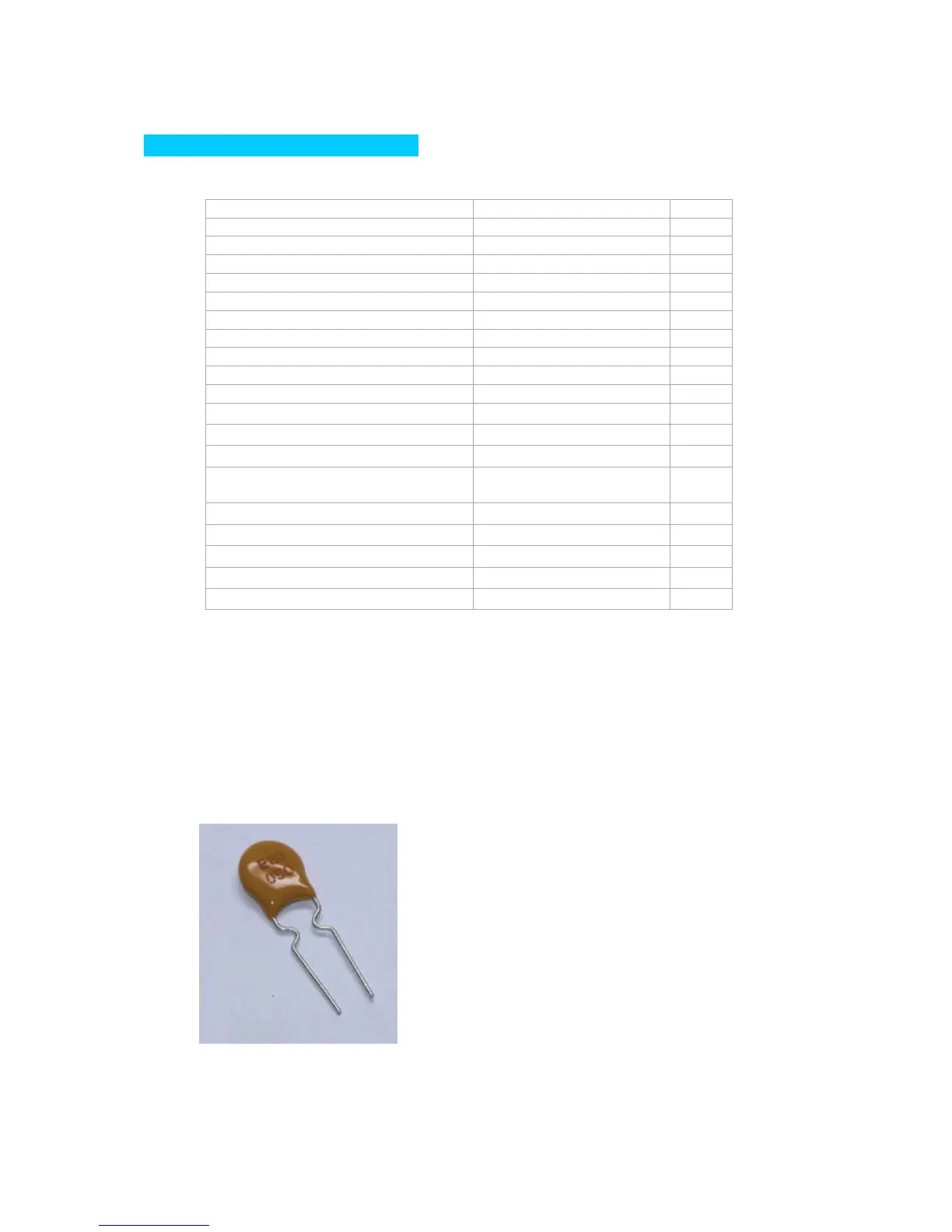
Please note the fuse will look like the picture below. It can easily be
confused for a capacitor. It is a self-resetting fuse.
 Loading...