EasyManua.ls Logo

PWM RTD1210 - User Manual

Default Icon
2 pages
Print Icon
To Next Page IconTo Next Page
Loading...
Users Manual
SAFETY INSTRUCTIONS
1.Make sure you r battery has enough voltage for the controller to
recognize the battery type before first installation.
2.The battery cable should be as short as possible to minimize loss.
3.The regulator is only suitable for lead acid batteries: OPEN,AGM, GEL
it is not suited for nickel metal hydride , lithium ions or other batteries.
4.The charge regulator is only suitable for regulating solar modules.
Never connect another charging source to the charge regulator.
PRO DUCT FEATURES
1.Build-in industrial micro controller.
2.Big LCD display,with 5V USB charg er
3. PWM charge management.
4.Build-in short-circuit protection,open-circuit protection,reverse
protection,over-load prote ction.
5.Dual mosfet Reverse current protection ,low heat production.
SYSTEM CONNECTION
1.Connect the batte ry to the charge regulator - plus and minus.
2.Connect the photovoltaic module to the regulator - plus and minus .
3. Connect the consumer to the charge regulator - plus and minus.
The reverse order applies when dei nstalling!
An improper sequenc e order can damage the controller!
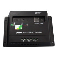
DISPLAY
Display the battery voltage
This iron will be on when solar panel volt age is higher
than battery voltage,and it wil l start charging.
Battery power iron
If this iron flashes means the battery voltage is too
low and the output will be cut off until t he battery
voltage raise to 12.6V
Iron on means output is good.
TROUBLE SHOOTING
Situation
Probable cause Solution
Charge icon not on
when sunny
Solar panel opened
or reversed
Reconnect
Load icon off Mode setting wrong Set again
Battery low recharge
Load ico n slow flashing
Over load Reduce load wat t
Load ico n slow flashing Short circuit protection
Auto reconnect
Power off
Battery too low/reverse Check battery/connection
TECHNI CA L PARAMETER
MODEL
RTD1210 RTD1220 RTD1230 RTD4810 RLD4820
Batt voltage
12V/24V auto 48V
Charge current
10A 20A 30A 10A 20 A
Discharge
current
10A 20A 30A 10A 20 A
Max Solar input <50V <80V
Buck charge
14.5V
Float charge 13.7V
Discharge stop 10.7V
Dis charge reconnect
12.6V
USB output
5V/0.8A
Self-consume <10mA
Control mode PWM
Operating
temperature
-35~+60
Size/Weight
150*78*35mm /150g
*all red color voltage X2 ,X4 while using 24V /48V system.
*Product specifications are subject to change without prior notice.
Question and Answer IconNeed help?

Do you have a question about the PWM RTD1210 and is the answer not in the manual?

Overview

This document describes a solar charge controller, a device designed to manage power flow from solar panels to batteries and connected loads. It features a built-in industrial microcontroller and PWM (Pulse Width Modulation) charge management, ensuring efficient and safe charging of lead-acid batteries.

Function Description

The solar charge controller acts as an intermediary between solar panels, batteries, and DC loads. Its primary functions include:

  • Charge Management: It regulates the voltage and current coming from solar panels to charge the battery efficiently and prevent overcharging. The PWM charge management optimizes the charging process, extending battery life.
  • Load Control: It manages the power supply to connected DC loads, protecting them from over-discharge of the battery. It can automatically disconnect loads if the battery voltage drops too low and reconnect them when the battery has sufficiently recharged.
  • System Monitoring: The device features a large LCD display that shows real-time system information, including battery voltage, charge current, discharge current, and operational status.
  • Protection Features: It incorporates multiple protection mechanisms to safeguard the system components. These include short-circuit protection, open-circuit protection, reverse polarity protection, and overload protection.
  • USB Charging: A built-in 5V USB charger allows for convenient charging of small electronic devices.

Important Technical Specifications

The manual provides specifications for several models: RTD1210, RTD1220, RTD1230, RTD4810, and RLD4820, catering to different current requirements and system voltages.

  • Battery Voltage:
    • 12V/24V auto-sensing for RTD1210, RTD1220, RTD1230 models.
    • 48V for RTD4810 and RLD4820 models.
  • Charge Current:
    • 10A for RTD1210, RTD4810.
    • 20A for RTD1220, RLD4820.
    • 30A for RTD1230.
  • Discharge Current:
    • 10A for RTD1210, RTD4810.
    • 20A for RTD1220, RLD4820.
    • 30A for RTD1230.
  • Max Solar Input Voltage:
    • <50V for 12V/24V systems.
    • <80V for 48V systems.
  • Buck Charge Voltage: 14.5V (for 12V systems, multiply by X2 for 24V, X4 for 48V).
  • Float Charge Voltage: 13.7V (for 12V systems, multiply by X2 for 24V, X4 for 48V).
  • Discharge Stop Voltage: 10.7V (for 12V systems, multiply by X2 for 24V, X4 for 48V).
  • Discharge Reconnect Voltage: 12.6V (for 12V systems, multiply by X2 for 24V, X4 for 48V).
  • USB Output: 5V/0.8A.
  • Self-Consume: <10mA.
  • Control Mode: PWM.
  • Operating Temperature: -35°C to +60°C.
  • Size/Weight: 1507835mm / 150g.

Usage Features

  • System Connection: The manual outlines a specific connection order:
    1. Connect the battery to the charge regulator (plus and minus).
    2. Connect the photovoltaic module to the regulator (plus and minus).
    3. Connect the consumer (load) to the charge regulator (plus and minus). The reverse order applies when uninstalling. An improper sequence can damage the controller.
  • Battery Compatibility: The regulator is suitable only for lead-acid batteries (OPEN, AGM, GEL). It is not compatible with nickel metal hydride, lithium-ion, or other battery types.
  • Solar Module Compatibility: The charge regulator is designed exclusively for regulating solar modules. Connecting another charging source to the regulator is explicitly prohibited.
  • LCD Display: The large LCD provides clear visual feedback on the system's status. It displays battery voltage, charging status (charging, floating, discharge stop), and load status.
  • Troubleshooting Guide: The manual includes a troubleshooting section to help users diagnose common issues:
    • Charge icon not on when sunny: Possible causes include an open or reversed solar panel connection, or incorrect mode settings. Solutions involve reconnecting the panel or setting the mode again.
    • Load icon off: Indicates a possible battery low condition or incorrect mode setting. Solutions include recharging the battery or setting the mode again.
    • Load icon slow flashing: Suggests an overload condition. The solution is to reduce the load watt.
    • Load icon slow flashing (different context): Can also indicate short-circuit protection. The solution is auto-reconnect.
    • Power off: May be due to the battery being too low or reversed. The solution is to check the battery and its connection.
  • Visual Indicators: The display uses specific icons to convey information:
    • A solar panel icon indicates that the solar panel voltage is higher than the battery voltage, and charging is in progress.
    • A battery icon indicates the battery's power level.
    • A flashing battery icon signifies that the battery voltage is too low, and the output will be cut off until the battery voltage rises to 12.6V (for 12V systems).
    • A solid "iron" icon (likely referring to the load output icon) indicates that the output is good.

Maintenance Features

  • Battery Voltage Check: Before initial installation, ensure the battery has sufficient voltage for the controller to recognize its type.
  • Cable Length: Keep battery cables as short as possible to minimize power loss.
  • System Protection: The built-in protections (short-circuit, open-circuit, reverse polarity, overload) automatically safeguard the system, reducing the need for manual intervention during faults.
  • Dual MOSFET Reverse Current Protection: This feature helps in low heat production, contributing to the device's longevity and stable operation.

The manual emphasizes that product specifications are subject to change without prior notice, and all red color voltage values should be multiplied by X2 for 24V systems and X4 for 48V systems.

PWM RTD1210 Specifications

General IconGeneral
BrandPWM
ModelRTD1210
CategoryInverter
LanguageEnglish

Related product manuals