www.proindecsa.com / proindecsa@proindecsa.com
MANUAL DE INSTALACIÓN Y MANTENIMIENTO
CONTROLADOR AUTOMÁTICO
3
CONEXIONADO ELÉCTRICO
ARRANQUE, OPERACIÓN Y PARADA DE LA BOMBA
MANTENIMIENTO
DIMENSIONES DE LA INSTALACIÓN
Precaución:
• Asegúrese de que el voltaje (V), frecuencia (Hz) y fase (PH) son conformes a los
etiquetados.
• La bomba debe presentar un correcto conexionado a tierra y un sistema de protección
frente a pérdidas.
• El cableado debe cubrir los requerimientos de la corriente.
• Asegúrese del correcto circuito eléctrico.
Precaución:
• Operación en seco está prohibido para evitar quemar el sello mecánico.
• Debe girar libremente a través de la tapa del ventilador mediante un destornillador.
• Al arrancar la bomba, se debe ver el giro del ventilador en el sentido de las agujas del
reloj.
• Rellene la bomba con agua desde la válvula de descarga.
• Arranque la bomba y establezca la presión de impulsión a la requerida.
• Cierre la válvula de impulsión antes de la parada de la bomba.
Aviso:
• Está terminantemente prohibido arrancar la bomba frecuentemente, se debe abrir el
interruptor cuando la potencia está cortada.
• No está permitido usar la válvula de aspiración para ajustar el caudal.
• Cuando el agua es insuciente, se debe parar el motor.
• Si hay algún ruido anormal, por favor, pare el motor y compruebe.
• Si la bomba se emplea durante periodos largos o bajas temperaturas, el agua debe ser
drenada para evitar daños en el cuerpo de la bomba como congelamiento.
2015-06
1
10. TROUBLE SHOOTING GUIDE
2
The pump does
not run
The pump does
not pump properly
The pump runs
but no water
The flow reduces
obviously
The motor is
over heat
The pump stops
soon after starting
The motor is locked.
The voltage is too low.
Bad ventilation in the operation room.
The motor is rocked.
The voltage does not match.
Fuse or thermal protector makes the
pump stop running.
The head is too high.
The water level is too low.
The bottom valve is not in the water.
No water.
The inlet pipe is leakage.
The foot-valve is blocked.
The impeller is corrosive.
The bottom valve is not in the water.
No priming water.
The inlet pipe is leakage.
The foot-valve is blocked.
The head is too high.
The water level is too low.
The impeller is serious damage.
The voltage does not match.
Bad ventilation in the operation room.
Send to the service center.
Check the voltage on the name plate.
Check the fuse or thermal protector.
Check the height of installation if it meets the head.
Check the suction height.
Have the valve in the water.
Fill the pump with water.
Check whether the pipe is leakage.
Check the suction height and re-install the pump.
Replace the impeller.
Fill the inlet section with water.
Fill the pump with water.
Check whether the pipe is leakage.
Disconnect the pipe and send to the service center.
Contact the electric power company to supply stable voltage.
Have good ventilation.
Contact the electric power company to supply stable voltage.
Have good ventilation.
Clean or replace the foot-valve.
Check the height of installation whether is the same as normal doing.
Check the suction height and re-install the pump.
Replace the impeller.
POSSIBLE REASONS SOLUTION PROBLEMS
9.PERFORMANCE CURVE
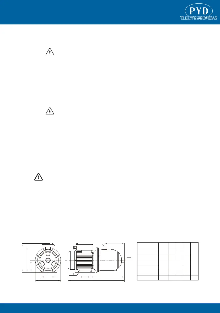
8.INSTALLATION SIZE
L
L
1
F
SBM203(T)
SBM204(T)
SBM205(T)
0.75
426
251 151
0.55
402
227 127
1.0
450
275 175
SBM403(T)
SBM404(T)
SBM405(T)
1.0
426
251 151
0.75
402
227 127
1.5
482
275 175
H
217
223
191
108
L
88 L1
F
G1
G1
H
190
90
4- 9
Model
Power
P2(kW)
0
IMP-G.P.M
5 10 15 20
SBM205(T)
SBM204(T)
SBM203(T)
SBM405(T)
SBM404(T)
SBM403(T)
60
50
40
30
20
10
0
H(m)
200
160
120
80
40
0
H(ft)
0
US.-G.P.M
5 10 15 20 25
0 12.5 25 37.5 50 62.5 75 87.5 100
0 0.5 1 1.5 2 2.5 3 3.5 4 4.5 5 5.5 6
3
Q(m /h)
Q(l/min)
Head
Flow
Modelo
P


 To Next Page
 Loading...