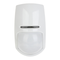
KX15DD
15m Digital PIR Detector
0845 6434 999 (UK). +44(0)1709 535 225 customer.support@pyronix.com www.pyronix.com Pyronix Limited, Pyronix House, Braithwell Way, Hellaby, Rotherham, S66 8QY, UK RINS1038-8
EN50131-2-2:2008
EN50131-1:2006+A1:2009
PD6662:2010
Security Grade 2
Environmental Class II
ENGLISH
(Diagram references)
Technical Specification
Warranty
Product Warning Information
This product is sold subject to our standard warranty conditions and is warranted
against defects in workmanship for a period of ve years.
For further warranty information visit: www.pyronix.com/warranty
For electrical products sold within the European Community. At the end of the
electrical products life, it should not be disposed of with household waste. Please
recycle where facilities exist. Check with your Local Authority or retailer for recycling
advice in your country. The declaration of conformity may be consulted at
www.pyronix.com/product-compliance.php
This product is approved for use in the Residential,
Commercial and Light Industrial Environments.
EOL
The KX15DD Printed Circuit Board
®
D
C3
AUTO HI
LOW AUTO
AUTO HI
LOW AUTO
AUTO HI
LOW AUTO
==
=
=
LOW
Model: KX15DD
Colour: White
LED Colour: Blue
Casing: 3mm ABS, 0.4mm HDPE in lens area
Detection Method: Digital Signal Processing
PIR Sensitivity: Auto (Default), High, Low
Temperature Compensation: Digital
Detection Range: 15m (13m by EN50131-2-2 & INCERT criteria)
Detection Speed: 0.3 - 3.0 m/s
Operating Voltage: 9 - 16V DC 13.8V DC typical
Current Consumption: 13mA @ 12V (Min), 16mA @12V (Max)
Relay Output: 50mA 60V DC, 42 VAC (RMS)
Contact Resistance: < 10 ohms
Mounting Height: 1.8 - 2.4m
Tamper Switch: 12V 50mA
Storage Temperature: -40
o
C to 80
o
C
Certied Operating Temperature: -10
o
C to 40
o
C
Nominal Working Temperature: -30
o
C to 70
o
C
Accessories: Wall and Ceiling brackets
Emissions: EN55022 Class B
Immunity: EN50130-4
HIGH
PCB
DEFAULT
PREDEFINITO
HIGH / LOW
B
START
f) Back
Tamper
C D
F G
E
1
A
B
2
C
D
3
A
LED ON LED OFF
1
A
B
C
Printed Circuit Board (PCB)
LED light pipe / diuser
Lens
D
E
F
G
Lens holder
PCB screw
Captive nut
Casing screw
2
33
34
PCB conguration (Including PIR sensitivity)
Mounting Options
The 15m Volumetric Lens. Dimensions and Weight
EOL Resistor Headers: The KX15DD has 2 sets of header pins (as shown). These
headers are used to select the End of Line resistance for EOL wiring applications.
NOTE: If EOL wiring is not used, leave the headers OFF.
Remote LED Enable: This is used when the LED is disabled via the LED ON/OFF
link. To enable this feature the LED terminal needs to be connected to an output
on the control panel. When the system is in walk test mode the output should
be at 0v. For Pyronix panels the output would usually be programmed as
‘Remote LED enable’.
Powering Up: When the detector is rst powered up, it will run through a self-test
routine (indicated by the ashing blue LED). Once the LED goes out the detector
is ready to use.
35
36
37
38
39
A
B
C
D
E
N/C - Normally Closed Wiring (EXAMPLE ONLY, SEE CONTROL PANEL INSTRUCTIONS)
PCX DEOL Wiring (EXAMPLE ONLY, SEE CONTROL PANEL INSTRUCTIONS)
EURO DEOL Wiring (EXAMPLE ONLY, SEE CONTROL PANEL INSTRUCTIONS)
Generic Control Panel (shows resistor locations)
2x Double End of Line Detectors to One Input (SEE CONTROL PANEL INSTRUCTIONS)
+
+
+
+
+
+
+
+
+
+
+
+
PIR
TAMPER
TAMPER
5K6, 4K7, 2K2, 1K
ALARM
6K8, 5K6,
4K7, 2K2, 1K
A
B
B
C
3
AUTO