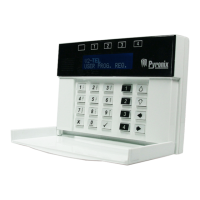
V2 GSM Installation Manual
Pyronix Ltd Page: 38
7.2 TECHNICAL SPECIFICATION
Voltage range: 10-14.9V DC
Quiescent current draw: 200mA
Maximum current draw: 800mA (average)
PGM1-4 (open-collector transistor outputs): 500mA max. each (500mA total)
Input voltage range: 0-15V DC - inputs have 39K resistor to 0V and 47K
to positive supply
Input trigger thresholds: Low=0-3.9V DC, high=8-12V DC @ 12V supply
Internal speaker: 500mW
External speaker: 1W @ 16 Ohms
External microphone supply: 250mA max.
Temperature: -20 to +40'C (operational)
7.3 OPENING THE V2 GSM
Loosen the screw on the underside of the V2 GSM.
Insert a wide flat-head screw-driver into each of the two lugs on the underside of
the V2 GSM (as shown below).
(Bottom of V2 GSM)
Lever the screwdriver and push the lugs inwards and pull the back of the V2 GSM
away from the front.
7.4 SCREW MOUNTING HOLES
Screw Holes

 Loading...