8 9INSTALLATION AND OPERATION MANUAL SOLAR MODULES Q.PEAK DUO ML-G9.X – Q CELLS INSTALLATION AND OPERATION MANUAL SOLAR MODULES Q.PEAK DUO ML-G9.X – Q CELLS
Specifications
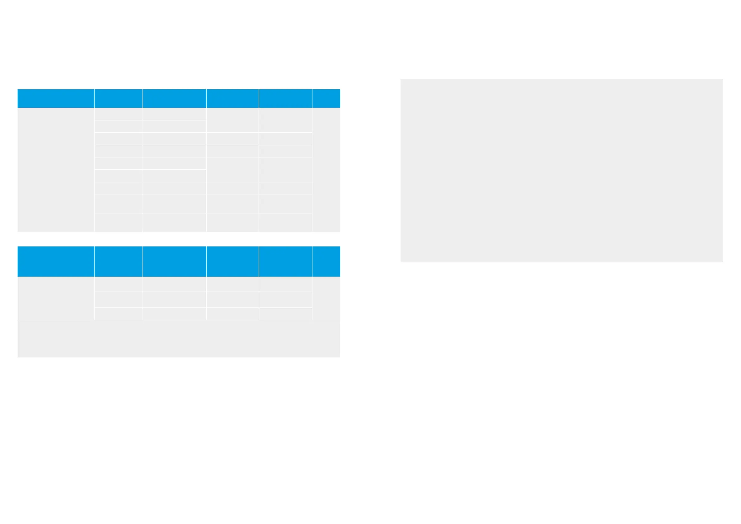
MODULE TYPE
MOUNTING
OPTION
POSITION OF
CLAMPS* [MM]
TEST LOAD
PUSH/PULL** [PA]
DESIGN LOAD
PUSH/PULL** [PA]
SAFETY
FACTOR
Q.PEAK DUO ML-G9
Q.PEAK DUO ML-G9+
Q.PEAK DUO BLK ML-G9
Q.PEAK DUO BLK ML-G9+
CL1a 150 - 450
5400/4000 3600/2660
1.5
FB1 376
FB2 376 3300/4000 2200/2660
IP1 - 3300/3300 2200/2200
CL1a 20 - 550
2400/2400 1600/1600
CL1b 20 - 550
CL3 250 - 450 3300/4000 2200/2660
CL5
short side: 100 - 250
long side: 300 - 450
3800/3800 2530/2530
CL6b
short side: 100 - 250
middle: 720 - 1120****
6000/4000 4000/2660
Ä The below mounting options are only possible under certain conditions.
MODULE TYPE
MOUNTING
OPTION
POSITION OF
CLAMPS* [MM]
TEST LOAD
PUSH/PULL***
[PA]
DESIGN LOAD
PUSH/PULL***
[PA]
SAFETY
FACTOR
Q.PEAK DUO ML-G9
Q.PEAK DUO ML-G9+
Q.PEAK DUO BLK ML-G9
Q.PEAK DUO BLK ML-G9+
CL2a (with
rails)
20 - 300 2400/2000 1600/1330
1.5
CL2b (without
rails)
20 - 300 2000/2000 1330/1330
IP2 - 2000/2000 1330/1330
*
**
***
****
Distance between outer edge of module and middle of the clamp; consider further details below.
Loads according to IEC 61215-2:2016 and UL 61730.
Test procedure according to IEC 61215-2:2016 and UL 61730. Loads for these mounting options do not fulfill the requirements of the standards.
Rails must not be under the junction box.
ATTENTION
Ä The loads in the table are related to the mechanical stability of the solar modules. The mechanical stability of the mounting
system including clamps has to be evaluated by the system supplier. The Q CELLS listed test load values were determined
with the following clamp parameters: clamp width = 40 mm and clamp depth = 10 mm. The system installer is responsible for
the determination of location-specific load requirements.
Ä CL1a at high loads (5400 / 4000 Pa): The clamp position is variable in the given range but the distance between the clamps
along the long side of the module (span) must not be larger than 1250 mm.
Ä CL1b: Using of short mounting rails are permissible, if they overlap under the module not more than 210 mm. Minimum height
of the short mounting rails should be ≥ 35 mm (clearance between frame bottom edge and roof top).
Ä Ensure, that the subconstruction does not touch the junction box (even under load). Ensure that the clamps or insertion profiles
etc. do not touch the glass (even under load).
Ä Ensure, that the connection cables of the junction box do not run between laminate and mounting rails.
Ä A minimum support depth of 15 mm is required on the back side of the module for IP1, IP2, CL2b, CL3 and CL6b. The minimum
required support depth on the module backside for CL5 is 10 mm on long frame side and 15 mm on short frame side. For IP1
and IP2 the minimum support depth on the front side of the module should be 10 mm.
Ä CL1a, CL2a and CL3: Ensure that module frame is fixed directly on the rail of the substructure (no spacer allowed between
the module and substructure).
Ä Module bends under load. Therefore, sharp objects (e.g. screws) must not be mounted near the module backside.
Ä Unbalanced snow loads (e.g. snow overhangs, snowdrifts) which result in locally significantly increased loads must be removed
or avoided by technical measures.
Ä Use M8 corrosion-proof screws and washers (diameter ≥ 15.8 mm or ≥ 0.62 in) for FB1 and FB2 mounting. Mounting screws
and washers should have the same material properties.
2 PLANNING 2 PLANNING
2.3 MOUNTING OPTIONS 2.3 MOUNTING OPTIONS
 Loading...