INTRODUCTION
This guide explains how to install a QETTLE Leak Detector. The
guide covers the installaon process for installing the Leak
Detector in conjuncon with a new QETTLE system, or when retro-
ng to an exisng QETTLE installaon. Correctly installed and
properly maintained in accordance with the following instrucons,
it will provide you with many years of reliable service.
Study the diagrams, read this guide and plan the layout carefully
before proceeding.
PLAN THE LOCATION FOR THE LEAK DETECTOR
• IMPORTANT NOTE: The leak detector must be posioned on the base of the kitchen cabinet, on a at surface, with the 2 x
metal plates facing down. The 2 x metal plates must be in contact with the base of the cabinet.
• The opmum locaon for the leak detector is an area between the boiler tank, undersink chiller (if applicable), and the
lter housing. The goal with selecng the locaon is to place the leak detector in the best locaon to detect leaks from any
component of the system.
• Ensure the selected locaon for the leak detector is within reach (1.5 metres) of the Auto-Shut O Valve.
• IMPORTANT NOTE: Always install the leak detector in conjuncon with the mechanical shut-o valve supplied with all
QETTLE systems.
TECHINCAL DATA
Operang Voltage: 9V DC
Cable Length: 1.5M
Connecons: 1/2” BSP Female to 1/2” BSP Male
Minimum Operang Temperature: 20°C
Maximum Operang Temperature: 80°C
Maximum Pressure: 5 BAR (73psi)
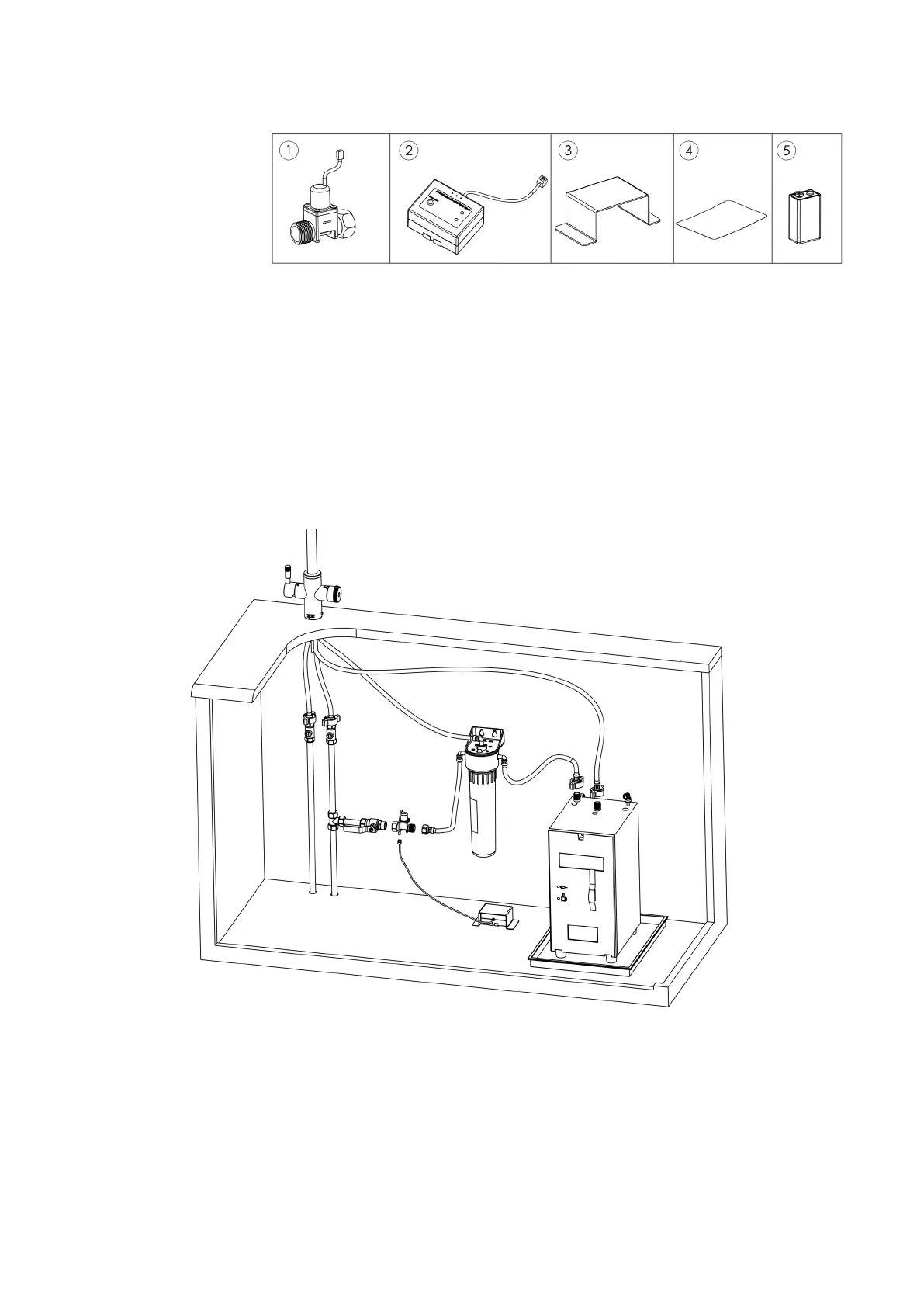
COMPONENT LIST
1. Auto-Shut O Valve
2. Leak Detector
3. Leak Detector Cover
4. Label
5. 9V Baery
 Loading...