Do you have a question about the QHYCCD QHY268PRO M and is the answer not in the manual?
Details on native 16-bit A/D, BSI technology, zero amplifier glow, TRUE RAW data, anti-dew, and advanced cooling.
Highlights advantages like higher data rates (10Gbps) and significantly longer transfer distances compared to USB3.0.
Describes the user-friendly USB3.0 interface and the versatile GPIO socket for custom configurations.
Details on air and water cooling performance, specifying typical temperature reductions below ambient.
Explains Photographic, High Gain, and Extended Fullwell modes and their characteristics.
Presents dark current vs. temperature data and quantum efficiency curves for monochrome and color sensors.
Details the installation process for the driver, SDK, and software package for Windows.
Specifies the required input voltage range (11V-13.8V) and considerations for power cables.
Guides users on connecting the camera to the computer via USB3.0 after power connection.
Covers overview, camera connection, and temperature control functionalities.
Instructions for launching SharpCap and initial camera connection.
Covers camera connection, offset adjustment, RAW16 mode, and thermal controls within SharpCap.
Explains using ASCOM drivers with compatible astronomy software packages for seamless operation.
Instructions for connecting N.I.N.A. software via ASCOM for astronomical imaging.
Step-by-step guide for configuring ASCOM drivers and connecting to astronomy software like Maxim DL.
Instructions on how to use the TE cooler to set the desired camera temperature.
Describes the QHYCCD Broadcast WDM Camera driver for video streaming to other applications.
Steps for installing the Broadcast WDM Camera driver through the AllInOne package.
Selecting optional components like drivers and SDKs during the AllInOne installation.
Activating the broadcast function, typically using SharpCap as the terminal software.
Displays test results and rendering effects for common supporting software like AMcap, HANDYAVI, and UFOCAPTURE.
Notes on system requirements (Windows only) and SDK limitations (no 16-bit support).
Provides links to download Debug TOOL and Release TOOL for advanced control.
Details on configuring BD/GPS mode and GPIO port functions, including TrigOut and specific port assignments.
Configures all four GPIO ports for generic output, controllable via API.
Sets GPIO ports for GPSBOX communication, including clock, data, and shutter measure signals.
Configures GPIOs for TrigOut, ShutterMeasure, TrigIn, and LinePeriod, with specific input/output assignments.
Covers MODE3 GPIO configuration, overview of MODE4-6, and procedures for CMOS chamber drying and cleaning.
Tips to prevent CMOS chamber fogging and advice on TE cooler thermal shock avoidance.
Explains Under Voltage Locking, its warning execution, and its purpose in device protection.
Covers power supply improvement, clearing UVLO protection, and investigating UVLO warnings due to voltage drop.
Explains UVLO detection methods, Burst Mode functionality, and key usage notes.
API functions for enabling Burst Mode, setting start/end frames, and managing IDLE status.
APIs for DDR patching, frame counter reset, and image data display (OSD).
Demonstrates the sequence of API calls for Burst Mode operation, including DDR setup and frame capture.
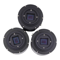
The QHY268 Pro M is a high-performance APS-C format CMOS camera featuring the Sony IMX571 sensor. It is designed for astronomical imaging and offers a range of advanced features for optimal performance.
The QHY268 Pro M is a monochrome camera equipped with a back-illuminated 26-megapixel sensor. It boasts a native 16-bit ADC, providing 65536 levels of output for high sample resolution and low read noise. The back-illuminated structure enhances full well capacity, particularly beneficial for small pixels, by allowing light to enter the photosensitive surface from the reverse side, minimizing photon loss due to metal wiring. This design results in a high quantum efficiency of up to 91%, ensuring efficient conversion of photons to electrons and increased sensitivity for capturing faint objects. The camera also features zero amplifier glow, eliminating a common issue in astronomical imaging.
The camera supports multiple readout modes, each offering different performance characteristics. These modes are compatible with QHY ASCOM Camera Driver, SharpCAP software, and N.I.N.A software. The "Photographic Mode" is recommended for long exposures, allowing users to adjust gain for increased full well capacity. The "High Gain Mode" provides a switch point between LGC and HGC for optimal gain settings. The "Extended Fullwell Mode" offers improved full well values and system gain while reducing read noise.
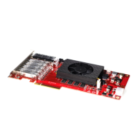
For data transfer, the QHY268 Pro M offers both USB3.0 and a built-in 2*10Gbps fiber socket. The fiber interface provides significantly higher data rates (up to 1.6 GBytes/s with two fibers) and longer transfer distances (up to 40km) compared to USB3.0 (3-5 meters). It also ensures solid and stable data transfer, unaffected by electromagnetic interference (EMI), which can cause data packet errors and image loss with USB cables.
The camera includes a 6-pin GPIO socket on the backside, which can be configured for various modes or customized for complex timing requirements by reprogramming the FPGA.
Installation and Software: The camera requires the "All-In-One" Pack (Driver, SDK, and Software) for Windows, available on the QHYCCD website. This pack includes the System Driver, WDM Broadcast Driver, EZCAP_QT (for device tests and updates), ASCOM drivers (for filter wheels), CP210X_VCP serial driver, SDKs for third-party software, and SharpCAP. It is crucial to install third-party capturing software before the All-in-one package.
Power Requirements: The camera operates on an input voltage between 11V and 13.8V. A 12V power supply is ideal, but users should ensure the cable has low impedance to prevent voltage drops, especially for long cables. The input voltage should not drop below 11.5V for normal operation.
Cooling Control: The camera's CMOS temperature can be controlled via software like EZCAP_QT or SharpCap. Users can set a target temperature (e.g., -10C) for automatic cooling or manually adjust the TEC power percentage. Gradual adjustment of TEC power is recommended to prevent thermal shock and extend the life of the TEC cooler.
Offset Adjustment: To improve image contrast and dark field quality, users can adjust the offset, particularly when completely blocking the camera (e.g., taking a dark frame).
16-bit Image Mode: The camera supports a "RAW16" mode for 16-bit image capture and an "LX" mode for expanding the exposure setting range for long exposures.
ASCOM Support: With ASCOM drivers, the QHY268 Pro M is compatible with various astronomical imaging software packages that support the ASCOM standard, such as Maxim DL and The SkyX.
Broadcast WDM Camera Driver: This driver enables the camera to function as a broadcast device, allowing video images to be sent to other WDM-supported software for online broadcast applications.
Burst Mode: The camera supports a Burst mode, a sub-mode of continuous mode, which allows the camera to output image data with a specified frame number. This feature is useful for capturing a series of frames efficiently.
UVLO Function: The camera incorporates an Under Voltage Locking (UVLO) function to protect electronic devices from damage due to abnormally low voltages. If the input voltage drops below 11V, the camera will issue a warning, automatically turn off the cooler, and enter TEC protection mode (limiting cooler power to 70%). This protection can be reset via EZCAP_QT once the power supply issue is resolved.
CMOS Chamber Drying: The camera's CMOS chamber has a hole for connecting a silica gel tube. If moisture causes the sensor glass to fog, users can connect a silica gel tube with desiccant to dry the chamber.
CMOS Sensor and Optical Window Cleaning: If dust accumulates on the CMOS sensor, the front plate of the camera can be unscrewed for cleaning. A cleaning kit for SLR camera sensors should be used. Caution is advised due to the AR (or AR/IR) coating on the CMOS sensor, which can scratch easily. Excessive force should be avoided when cleaning.
Preventing Fogging: To prevent condensation in the CMOS chamber, the QHY600 has a built-in heating plate. If fogging persists, users can try avoiding directing the camera downwards, increasing the CMOS sensor temperature slightly, or checking if the heating plate is functioning correctly (it should reach 65-70 °C at 25 °C ambient).
TEC Cooler Maintenance: To prolong the life of the TEC cooler, users should avoid thermal shock. This means gradually increasing and decreasing TEC power when starting or disconnecting the power supply, rather than abruptly turning it on or off at maximum power.
| Brand | QHYCCD |
|---|---|
| Model | QHY268PRO M |
| Category | Digital Camera |
| Language | English |