
 Need help?
Do you have a question about the Qomolangma FMJ-1400-WA-PLUS and is the answer not in the manual?
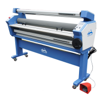
This document describes the Qomolangma® Brand Full-Auto Wide Format Cold Laminator, with Heat Assisted, an ideal partner for photographers, printers, and sign-makers. This laminator is designed to provide a simple and relaxed lamination experience, producing professional-quality finishes that can enhance business image and generate more sales leads.
The laminator's primary function is to apply a protective layer to various materials, giving them a finished, professional look. It excels in both cold laminating and mounting applications, with heat assistance to address issues like hazy cold-laminated images. The device is electrically driven and includes a floor stand and a foot pedal switch for convenient operation. Its versatility allows for a wide range of applications, including sign and display graphics, window graphics, banners, posters, point-of-purchase (PoP) displays, vehicle wrapping, wallpaper, cutting sheet stickers, labels and decals, proofs, package finishing, sign boards, flyers, document finishing, floor graphics, and both rigid and flexible indoor displays.
The Qomolangma laminator is designed with user-friendly operation in mind. Its control panel is easy to understand, allowing for straightforward operation. The machine features a hand crank and an automatic motorized lifting system for the upper roller, which provides greater stability and meets high-end needs compared to pneumatic lift systems. This design also reduces issues associated with air pressure. The rubber rollers are made of high-quality material, ensuring greater elasticity and durability. The machine's high-precision design, with a frame and bars cut by highly precise laser, ensures that the unwind shaft is parallel, preventing wrinkles and air bubbles during lamination. Loading and unloading rolls of materials can be done in seconds. For safety, the laminator is equipped with photosensitive cells that provide automatic self-control of safety devices and emergency buttons.
The installation process requires careful attention to ensure optimal performance and safety. Before unpacking, it's crucial to check for any damage during transportation. After unpacking, verify that all service parts match the packing list. The installation area should be spacious, dust-free, and devoid of vapor, corrosive gases, or combustible/explosive substances. It's important to keep the machine away from drafts, as this can affect roller temperature and lamination quality. After installation, adjust each caster to ensure the machine is level. Casters are intended for short-distance movement on even ground. The machine is heavy, so caution is advised during movement.
The stand floor rack assembly involves taking parts from the packing, assembling the two legs and all shafts as per the provided diagram, and installing the casters (two with brakes and two without, installed diagonally). The machine assembly involves connecting the main unit to the shaft using M10 screws, paying attention to the shaft direction. The four corners are fixed with M10 screws. When moving the machine, it's important to handle it by the bottom plate and avoid moving it by the hand wheel, friction wheel, or other delicate parts. The working table installation involves placing the front table in a diagonal position, aligning its front opening with the front screw, gently lowering it to align the rear gap with the rear screw, and then locking the bolt. Red supporting parts on both ends of the roller must be removed before operation. Finally, the foot pedal and wiring should be connected as illustrated. After setup, turn on the machine, rotate the roller, and perform a trial lamination to check the result.
The foot pedal offers an alternative way to control the start and stop of roller rotation. Pressing the foot pedal and then the direction button adjusts the speed, and releasing the pedal stops the rollers. It's important to note that the protective sensor is not active when the foot pedal is in use, so extra caution is needed to protect hands during foot pedal operation. The working table and pressure board are used to apply tension to media and ensure it's parallel with the film edge. Both are movable; the working table can be removed for media installation/uninstallation or roller cleaning, and the pressure board can be removed during lamination preparation and replaced once ready. To remove the working table, press the button to open the plug, then hold the middle and lift, and finally hold the middle and pull out. The pressure board can be lifted and removed, with screws inserted into its holes for storage on the back.
The machine features four shafts: film liner rewinder (A), film unwind shaft (B), media rewinder (C), and media unwind shaft (D). These shafts are interchangeable. The film liner rewinder and media rewinder are motorized, while the film unwind shaft and media unwind shaft are non-powered. To install or remove a shaft, take off the key from the saddles and move one side of the shaft out. For assembly, the left side should be installed first, ensuring the driven end of each shaft engages a key. Three rubber strips on each shaft hold the paper tube in place. Friction wheels (A, B, C, D) adjust friction: clockwise rotation increases friction, and anti-clockwise rotation decreases it. Adjusting the friction wheel helps achieve optimal lamination results. The machine has four casters; two (A) can be locked to prevent movement, and two (B) are without brakes.
For Warm series models, a temperature-measuring device is present, with a brass contact material that is sensitive, small, and durable. A pressure limit device prevents the hand crank from being used beyond a certain point, protecting the speed controller and ensuring maximum roller pressure. A 1300W stainless heater is located inside the roller for Warm series models; avoid touching the connection end to prevent electric shock. Periodically check and fasten the nuts if loose, and power off the machine when changing the heater.
The drive system uses a sprocket wheel for film unwind drive liner take-up. Different sprocket teeth numbers result in varying running speeds, which can be adjusted using the two-brake tension knob. The motor drives the roller and media take-up via the sprocket wheel.
The control panel includes indicator lights for "Warm" (hot laminating), "Cold" (cold laminating), and "Ready" (temperature reached). A display screen shows current and set temperatures. Up and Down tabs adjust the set temperature. A direction switching button controls motor rotation. A button starts or stops the heating function. An auto and pedal conversion switch allows selection between modes. A speed control button adjusts roller speed. Temperature settings can be accessed by pressing and holding the "Up" tab for 3 seconds. The default temperature unit is °C, with a temperature adjustment range of -30 to 30°C, a temperature alarm at 60°C, and a maximum temperature of 40°C. Factory specifications should not be changed randomly. The top roller typically takes 20 minutes to reach 40°C. It's normal for the temperature display to differ from room temperature when heating begins.
Regular maintenance is crucial for extending the machine's lifetime and ensuring optimal performance. Only experienced operators should open the cabinet. Abrasive cleaners should not be used on the machine surface. Rotation parts should be checked regularly, and high-temperature grease applied to lubricate the heating roller bearings. The machine should not be washed with water, as this can damage electrical circuits, cause electric shock, or corrosion. During maintenance, the machine should not be running, and safety parts should not be changed, moved, or dismantled. Always ensure safety parts are functional before use. The power supply must be cut off before any dismantling or assembly.
The main rollers are critical for lamination quality and require regular maintenance. After use, lift the upper rollers to prevent deformation. Ensure that knives or sharp items do not scratch the rollers. To extend roller lifetime, keep them clean by removing adhesive residue with a flannelette cloth, alcohol, detergent, or eraser. When wiping rollers, stop heating and ensure the temperature is below 40°C. Gently wipe rotating rollers, avoiding concentrated wiping at one point to prevent partial damage to the roller surface. Clean residual glue on the rollers, as it can affect lamination quality.
Roller replacement involves several steps: open both side cabinets, remove the heater wiring (after powering off the machine), remove the gear, remove the entire block bearing set and heater, remove the collars on the left cabinet, take off the roller, install the new roller, and then repeat the previous steps in reverse to reassemble the machine.
Regular checking of safety features is essential. Visually inspect the power supply cable for damage, ensure casters are stable, and check for any other machine damage. For the emergency switch, turn on the machine, press the switch to confirm it stops, then turn it on again, release the switch, and start the machine to verify its function. For the photocell checking, turn on the machine, ensure rollers are rotating, hide the photocell to check if rollers stop, then remove the obstacle to check if rollers resume rotation. Note that the optical switch does not work when the pedal switch is in use.
The document also provides troubleshooting for common problems, such as the motor not starting (due to power plug, voltage, emergency stop, or fuse issues), uncontrolled motor speed (potentiometer failure), rollers stopping intermittently (loose chains), and issues with film peeling or image off-tracking (damping or pressure imbalances). Solutions involve checking connections, voltage, emergency stop, fuse, replacing components, tightening chains, and adjusting damping or pressure. If the image is off-tracking, it indicates a pressure imbalance between the left and right sides, which needs adjustment. For cold lamination film, heating is not necessary, but if the working condition is below 10°C, heating to 40°C is recommended for optimal performance.
 General
| Max. Laminating Width | 1400 mm |
|---|---|
| Max. Laminating Speed | 10 m/min |
| Laminating Width | 1400 mm |
| Laminating Speed | 10 m/min |
| Warm-up Time | 10 minutes |
| Power Supply | 220V, 50/60Hz |

 To Next Page