7
TD-001543-01-C
Features
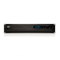
Front Panel
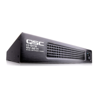
Rear Panel
— Figure 1 —
1. Power LED – illuminates blue when the
Q-SYS NV-32-H (Core Capable) is powered on
2. ID LED – LED blinks when placed into ID Mode via ID Button or
Q-SYS Core Manager/Peripheral Manager Software
3. ID Button – Locates the Q-SYS NV-32-H (Core Capable) in
Q-SYS Designer GUI and by Q-SYS Core Manager/Peripheral
Manager
— Figure 2 —
12
1. External Power Input 48 VDC 1.5 A – Auxiliary
power, 48 VDC, 1.5A, 2-pin Euro connector
2. LAN A/ PoE ++ – connection for Q-LAN network, 802.3bt
Type 4 power, RJ-45 connector
3. LAN B – RJ-45 connector, not active in peripheral mode. In Core
Mode, LAN B supports redundancy, VOIP, Control etc.
4. USB Type A – USB type A host connectors (blue connector
is for USB 3.0 connection). 1.0 A, total, is available for all four
Type-AUSBs.
5. GPIO Out
• 12 VDC Output – 12 V, 0.2 A output used for GPIO
signals.
• GPIO Outputs – 3 outputs, open collector (24 V, 0.2 A
maximum) with pull up to +3.3 V, pins 1-3 equal pins 1-3 in the
Q-SYS Designer GPIO Output component.
• Ground – Use this ground reference for 12 VDC and GPIO
outputs.
6. GPIO Inputs / RS-232
• GPIO Inputs – 2 inputs, 0-24 V analog input, or contact
closure, pins 1-2 equal pins 1-2 in the Q-SYS Designer GPIO
Inputcomponent.
• RS-232 – Transmit and Receive
• Ground – Use this ground reference for GPIO inputs and
RS-232.
7. Analog Audio Output – 3.5 mm connector unbalanced
stereo lineoutput
8. Analog Audio Input – 3.5 mm connector unbalanced
stereo mic/line input
9. USB B – USB Type B Device connector for web conference
integration
10. HDMI Inputs – HDMI 2.0 Input with support for HDCP 2.2 and
HDCP 1.4
11. HDMI Outputs – HDMI 2.0 Output with support for HDCP 2.2
and HDCP 1.4
12. Factory Reset – Use a paper clip, or similar tool, to press
and hold the reset button for 10 seconds to reset the NV-32-H to
factory values.
 Loading...