10
TSC-50-G3 In-Wall Mounting
The TSC-50-G3 is designed to be installed into single gang electrical boxes that are common in North America as well as circular
electrical boxes available in Europe. While a variety of single gang electrical boxes are supported, a rectangular box with a minimum
cavity of 18 cubic inches is recommended. For installations using a European circular back box, a minimum box depth of 60 mm is
recommended.
IMPORTANT!: Verify suitability of your selected electrical box, including LAN cable routing, prior to installation.
IMPORTANT!: Orientation of electrical box installation must match orientation of TSC-50-G3 wall mount bracket.
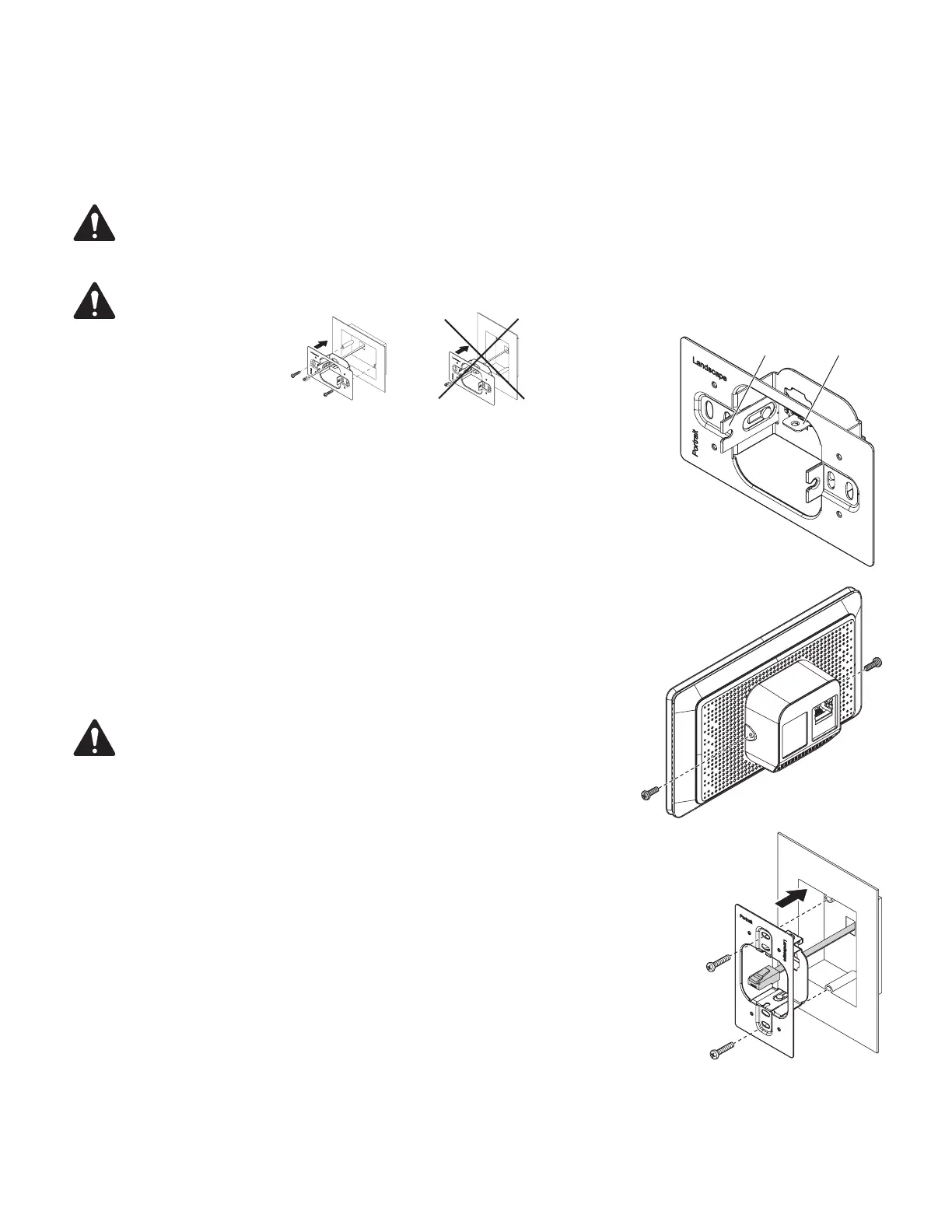
1. Prepare the TSC-50-G3 wall mount bracket for installation by pushing the sliding arm
forward so that the spring mechanism locks in place. See — Figure1.
2. Prepare the TSC-50-G3 for installation by partially installing two M2.5 screws into the sides
of the Touch Screen Controller. Install the screws approximately 1/2 turn in order to leave
sufficient space between the head of each screw and the side of the Touch Screen Controller
to accommodate the wall mount bracket arm. See — Figure2.
3. Ensure that the LAN cable includes sufficient length to provide proper stress relief.
4. Route the LAN cable through the cable opening in the wall mount bracket. See — Figure3.
5. Align the wall mount bracket to the electrical box and install using the supplied #6-32 screws.
When installing in portrait orientation, the word “Portrait” MUST be displayed in the upper-
left corner of the wall mount bracket. When installing in landscape orientation the word
“Landscape” MUST be displayed in the upper-left corner of the wall mount bracket.
See — Figure3
NOTE: Screws are not supplied for circular back boxes or alternate
mountingbrackets.
NoYes
— Figure1 —
Arm
— Figure2 —
— Figure3 —
 Loading...