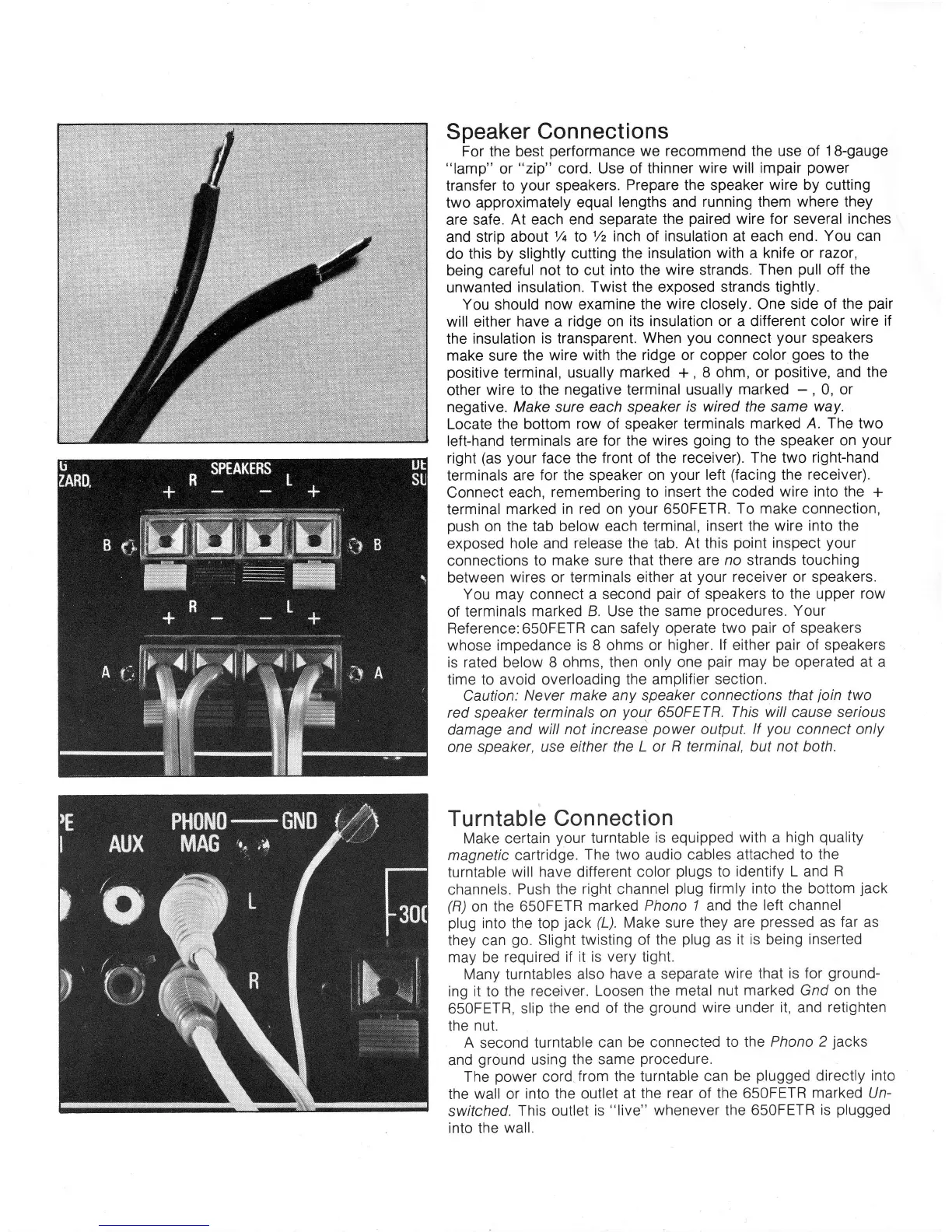
Speaker Connections
For
the
best
performance
we recommend the use of
1B-gauge
"lamp"
or
"zip"
cord. Use
of thinner
wire will impair
power
transfer
to
your
speakers.
Prepare the speaker
wire
by cutting
two approximately
equal lengths and
running them where they
are safe.
At
each
end separate
the
paired
wire for several
inches
and strip aboul1/t
to
% inch
of
insulation at each end.
You can
do this by slightly
cutting the
insulation with a knife or
razor,
being
careful not to cut
into the wire
strands.
Then
pull
off the
unwanted
insulation. Twist the exposed strands
tightly.
You
should
now examine the
wire closely. One side of the
pair
will
either
have a
ridge
on
its insulation or a different color
wire if
the insulation
is transparent. When
you
connect
your
speakers
make sure
the wire with the
ridge or copper color
goes
to the
positive
terminal, usually
marked
+,
8 ohm, or
positive,
and
the
other
wire to the
negative
terminal
usually marked
-
,
0, or
negative. Make sure each
speaker
is wired
the same
way.
Locate the bottom
row of speaker terminals
marked A.
The
two
left-hand terminals are
for the wires
going
to the
speaker on
yout'
right
(as your
face the front of the receiver).
The two right-hand
terminals are
for the speaker on
your
left
(facing
the
receiver).
Connect
each,
remembering
to
insert the coded
wire into the
+
terminal
marked in red on
your
650FETR.
To make connection,
push
on
the tab below each
terminal, insert the
wire into
the
exposed
hole
and
release the tab. At this
point
inspect
your
connections
to make sure that there are
no strands touching
between
wires
or terminals
either at
your
receiver
or
speakers.
You may connect a second
pair
of speakers to the upper
row
of terminals
marked B. Use the same
procedures.
Your
Reference:650FETR can safely operate
two
pair
of speakers
whose impedance
is
8 ohms or
higher.
lf
either
pair
of speakers
is rated
below
8 ohms, then only
one
pair
may be operated at a
time to avoid overloading
the amplifier section.
Caution:
Never make any speaker connections that
join
two
red speaker
terminals on
your
650FETR.
This willcause serious
damage
and
will not increase
power
output.
lf
you
connect only
one
speaker, use
either the L or
R
terminal, but
not
both.
Turntable
Connection
Make certain
your
turntable
is equipped
with
a
high
quality
magnetic cartridge.
The two audio cables
attached to the
turntable
will
have
different
color
plugs
to identify L and
R
channels.
Push the
right channel
plug
firmly into the bottom
jack
(R)
on the 650FETR
marked Phono 7 and
the left channel
plug
into the top
jack
(L).
Make sure
they are
pressed
as
far as
they can
go.
Slight twisting
of the
plug
as
it is being
inserted
may be
required if it
is very tight.
Many turntables
also
have a separate
wire that is for
ground-
ing it to the
receiver. Loosen the
metal nut
marked
Gnd on
the
650FETR,
slip
the end of the
ground
wire
under
it,
and
retighten
the nut.
A
second
turntable can
be connected
to the Phono 2
jacks
and
ground
using
the same
procedure.
The
power
cord
from
the turntable
can be
plugged
directly into
the wall or
into the outlet at
the rear of the 650FETR
marked Un-
switched.
This outlet
is
"live"
whenever the 650FETR
is
plugged
into the
wall.
 Loading...