CHASSIS ALIGNMENT
1. PIF Adjustment
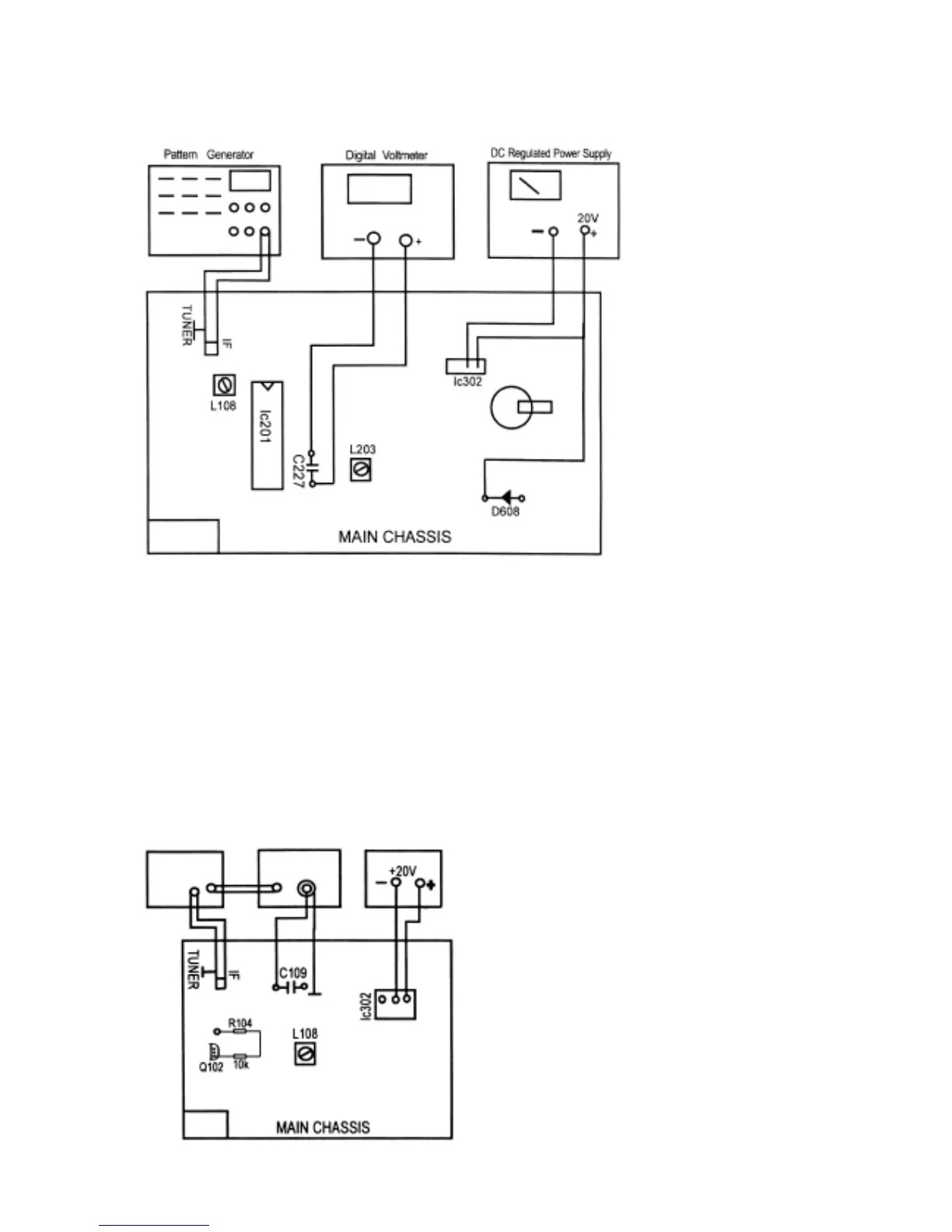
1-1 Tuner AGC connects to GND. Pattern Generator outputs 38.9MHz R.F. signal and connects to tuner
IF output terminal or pin 5 of saw filter.
1-2 Connect Digital voltmeter across C227. DC Regulated power supply positive terminal output +20V
to pin 1 of IC302 and negative terminal of D608. DC Regulated power supply negative terminal
connects to pin 2 of IC302.
1-3 Adjust L203 coil to obtain 3.6V Digital voltage meter reading.
2. System NTSC Adjust(L108)
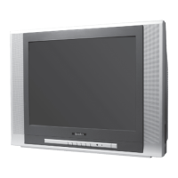
2-1 Tuner AGC connects to GND. Connect Sweep Signal Generator to tuner IF output terminal. Sweep
oscilloscope V-IN terminal connects to C109. And connect Q102 'b' pole to the power terminal of
R104. (shown in FIG.2)
Sweep Signal
Generator
Sweep
Osciloscope
DC Regulated
Power Supply