The Quantum Medical Imaging QS-500 Series Floor-to-Ceiling/Wall Tubestand is a medical imaging device designed for radiographic procedures. This manual provides comprehensive information for its installation, operation, and maintenance.
Function Description
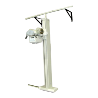
The QS-500 Tubestand is a floor-to-ceiling or wall-mounted support structure used to position a diagnostic x-ray tube housing assembly for medical radiographic procedures. It allows for precise positioning of the x-ray tube to acquire various radiographic views. The tubestand incorporates mechanical detents for angulation at 0°, 90° (CW), 90° (CCW), and indicators for vertical (40" and 72") SID positions to aid in equipment positioning.
Important Technical Specifications
The tubestand offers several key physical specifications:
- Column Height: 85.0 inches (2159.0 mm)
- Vertical Travel (x-ray tube): 60.5 inches (1536.7 mm)
- Tubestand Longitudinal Travel:
- 6' Track = 48.0 inches (1219.2 mm)
- 8' Track = 72.0 inches (1828.8 mm)
- 10' Track = 96.0 inches (2438.4 mm)
- Tube Angulation: 270° (+135°) with detents at 0°, 90° (CW), 90° (CCW)
- Counterbalancing: Counterweight (trim weight adjustable)
- Minimum Focal Spot-to-Floor Distance: 13.75 inches (349.0 mm)
- Collimator Compatibility: Manual, Selectable or Automatic, 10-20 lbs. (typical). Mounting to forty tube housing requires four 3/8-16 or M6 x 16 bolts spaced on a 3.625" diameter circle.
- Tube Compatibility: 3" or 4" rotating anode type, 30-40 lbs. (typical)
- Overall Weight: 508.0 lbs. (230.4 kg)
Electrical Specifications:
- Mode of Operation: Continuous
- Input Power: +24 VDC @ 1.0 Ampere
- Power Supply Type: Double (or Reinforced) Insulated (meets construction/performance criteria per UL 2601-1)
- Electrical Interfacing: Tubestand-mounted terminal strip for interfacing +24 VDC, tray sensing signals (with automatic collimator only)
Handgrip Specifications:
- Controls: Vertical, Longitudinal, Angulation, All Locks Release
- LED Indicators: 40" (100 cm) SID, 72" (180 cm) SID
- LCD Display (on systems equipped with digital handgrips only): 40" (100 cm) and 72" (180 cm) SID, tube rotation angle, date, time, x-ray generator technique selection when APR mode is activated (or mode [i.e., AEG/MANUAL] when not in APR mode)
- Angle Indicator Display (on systems equipped with analog handgrips only): Bubble type
Room Construction:
- A conventional radiographic room construction should be used in the area where the Tubestand is to be installed.
- Consult with your State Health Department or local Building Codes for specific radiation shielding requirements.
System Operating Environment:
- Ambient Temperature: +10°C to +40°C
- Relative Humidity: 20 to 80%, non-condensing
- Altitude: -30.5 to +2440 meters relative to sea level
Non-Operating Environment:
- Ambient Temperature: -18°C to +70°C
- Relative Humidity: 20 to 95%, non-condensing
- Altitude: -30.5 to +3048 meters relative to sea level
Usage Features
The QS-500 Tubestand is designed for ease of use and precise control during radiographic examinations.
- Movement Controls: The tubestand features three primary movements: longitudinal travel (head-to-foot) of the Vertical Column, vertical travel (SID adjust) of the Support Arm, and angulation of the X-Ray Tube/Collimator. These movements are controlled via handgrips with integrated lock release buttons.
- SID Indicators: LED indicators on the handgrips and an LCD display (for digital handgrips) show the 40" (100 cm) and 72" (180 cm) Source-to-Image Distance (SID) settings, crucial for accurate image acquisition.
- Angulation Display: The LCD display (or bubble type for analog handgrips) shows the tube rotation angle, allowing for precise angulation of the x-ray tube.
- Locking Mechanisms: Magnetic locks are used for longitudinal, vertical, and angulation movements, ensuring stable positioning once the desired settings are achieved. These locks are released by controls on the handgrips.
- Collimator Light Field: The manual includes instructions for verifying and adjusting the collimator light field versus the actual x-ray field, ensuring accurate beam alignment.
- Vertical Distance Scales: The tubestand features vertical distance scales on the front side of the Vertical Column to indicate the focal spot-to-film and focal spot-to-table top distance, with specific scales for "Bucky" vertical SID and "Table" vertical SID.
Maintenance Features
Regular maintenance is essential to ensure the continued integrity and safe operation of the QS-500 Tubestand.
- Cleaning: The painted metal surfaces should be cleaned using a clean cloth slightly moistened in warm soapy water (mild soap). Wipe with a clean wet cloth. Polishing agents should not be used.
- Daily Performance Checks:
- Visually inspect for wear and cleanliness.
- Clean Tubestand exterior surface.
- Every Six Months Performance Checks:
- Check for evidence of loose hardware or loose wires.
- Check all bearings and bearing surfaces for cleanliness and corrosion.
- Clean Bearing Tracks, Floor Track, and Top (ceiling/wall) Track.
- Conduct a general inspection for worn or damaged parts.
- Check for proper counterbalancing and smoothness of vertical (up/down) Tubestand motion.
- Replaceable Parts: The manual provides a list of replaceable parts for the Tubestand, including SID indicators, pushbuttons, SID switches, electromagnets, and fail-safe brakes. This list includes part numbers and quantities used on the system.
- Qualified Service Personnel: Routine inspection and maintenance of the Tubestand should be performed by qualified service personnel on an annual basis. This is crucial for safety and to ensure compliance with regulatory standards.
- Warning for Maintenance: Only properly trained service personnel should service or maintain this equipment. Failure to follow manufacturer's or service personnel's recommendations may result in serious injury.
- Electrical Safety: Before performing any electrical maintenance, ensure the power supply is turned OFF. In the event maintenance procedures require power to be supplied to the unit, extreme care MUST be exercised to insure the safety of service or other personnel in the area. Verify that the equipment is properly grounded before attempting any electrical operation.