Chapter 2 Assembly & Installation
Models QT-740 & QT-750 - Service Manual
13
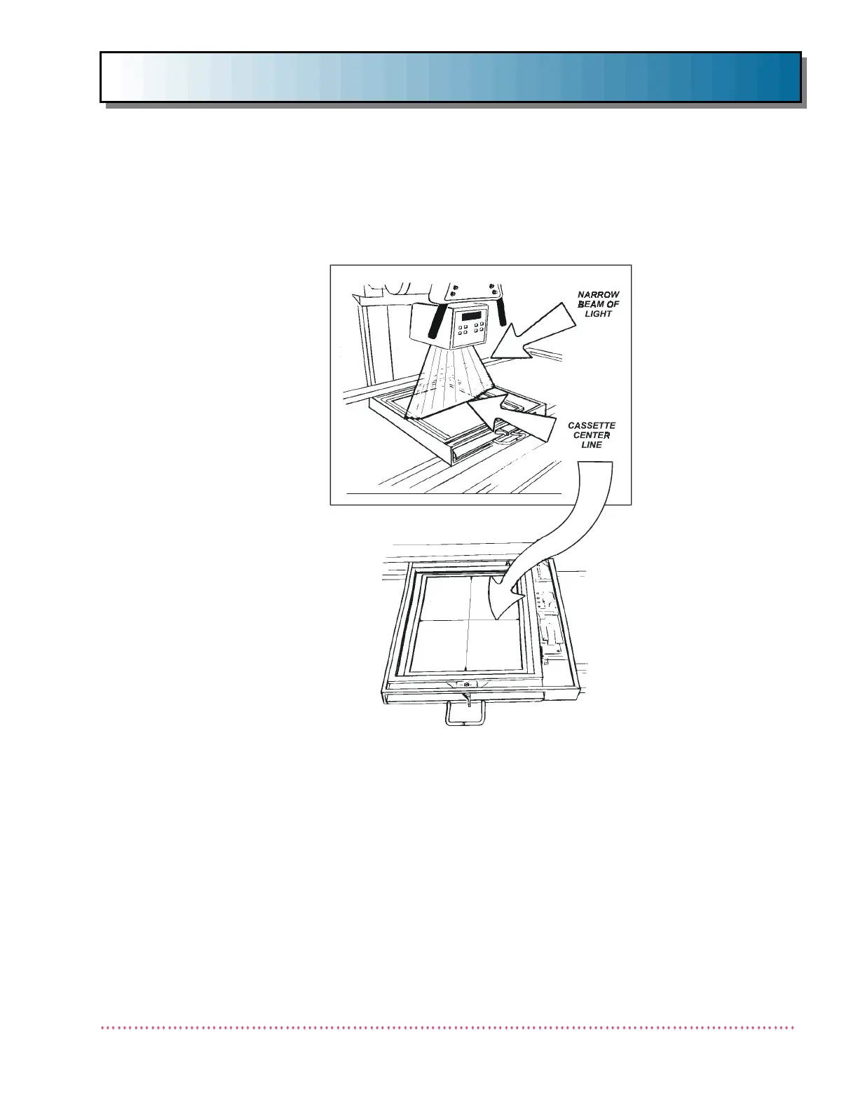
6. Turn on the collimator light and move the entire table so that the longitudinal
center line on the cassette (i.e., the line which is parallel to the length of the
table) is properly aligned with the narrow beam of light (see Figure 5).
7. Remove cable tie securing the Receptor Cabinet to tabletop frame.
8. Move the tubestand and Receptor Cabinet simultaneously to check for contin-
uous alignment of the narrow beam of light to the cassette center line (see
Figure 5).
9. If the light beam and cassette center line are in proper alignment, mount the
table through the 3/8" diameter holes in the front and back (be sure the lev-
eling shim plates are in the proper position). Use hardware suitable for the
type of floor in the installation and of sufficient strength to handle 500 lb.
pull-load.
Figure 5. Table Longitudinal Axis Alignment

 Loading...