Chapter 4 Service Instructions
40
Models QT-740 & QT-750 - Service Manual
6. Loosen two (2) bolts securing Sync Belt Switch to Sync Belt
Switch Bracket and remove Sync Belt Switch and set aside. (Do
not disconnect switch wires).
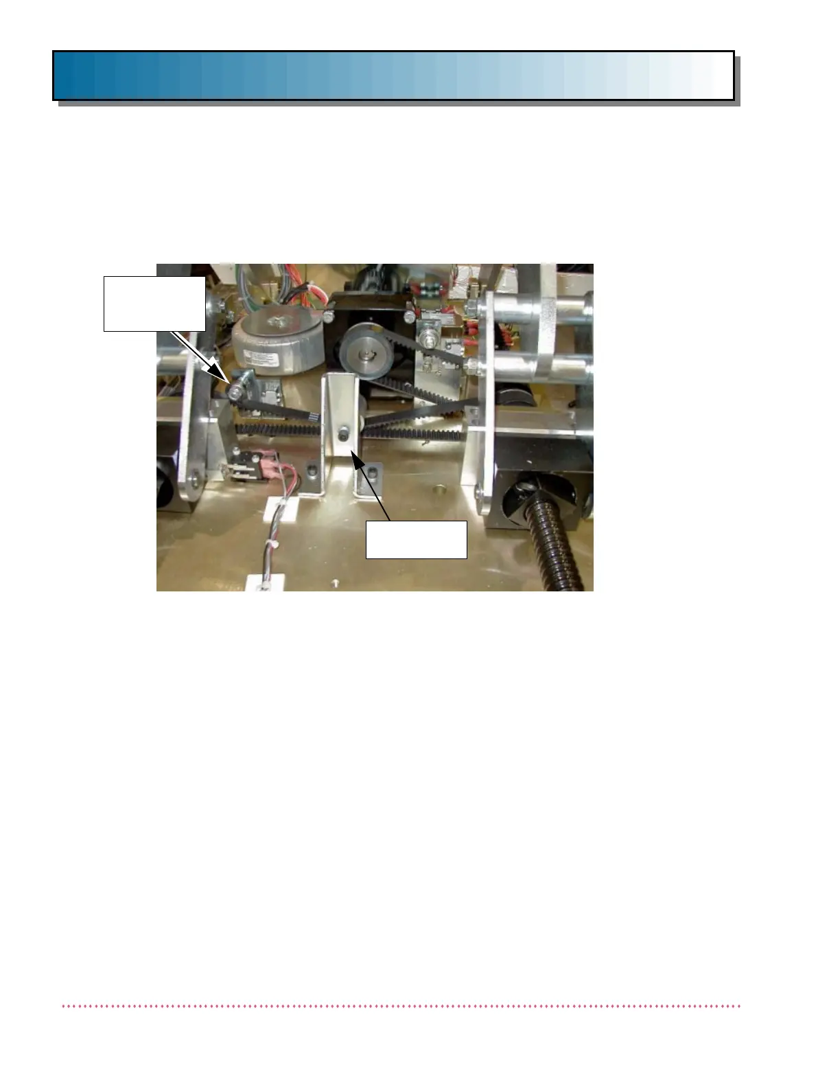
7. Loosen nut on Belt Tensioner to create slack in belt (see Figure
18). If necessary, remove Belt Tensioner to achieve sufficient
slack for belt removal.
8. Loosen two (2) 1/4-20 socket head cap screws securing Ball
Screw Mounting Block at pulley end of Lead Screw to Base Plate
(see Figure 18). Gently tap Block to remove it from Lead Screw.
9. Remove Sync Belt from pulleys.
10. Install replacement Sync Belt on pulleys.
11. Verify the distance between Ball Nut Blocks and center Ball Screw
Mounting Blocks (see Figure 19) are equal (±0.003"). If not,
rotate either shaft until distances are equal (within tolerance).
This is to ensure equal torque on both Lead Screws.
12. Install Ball Screw Mounting Block on pulley end of Lead Screw
and secure to Table Base Plate using two (2) 1/4-20 socket head
cap screws.
SYNC BELT
SWITCH
BRACKET
Figure 18. Location of Sync Belt Switch Bracket and Tensioner
BELT
TENSIONER

 Loading...