EasyManua.ls Logo

Quest Engineering PowerDry 1300 User Manual

Quest Engineering PowerDry 1300
13 pages
To Next Page IconTo Next Page
Page #1 background imageLoading...
Page #1 background image
quest
quest
DRY 150
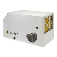
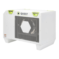
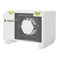
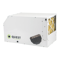
Quest PowerDry 1300
Installation, Operation and Maintenance InstructionsInstallation, Operation and Maintenance Instructions
– Read and Save These Instructions –
This manual is provided to acquaint you with
the dehumidier so that installation, operation
and maintenance can proceed successfully.
Ultimate satisfaction depends on the quality
of installation and a thorough understanding
of this equipment. The dehumidier is built
around tested engineering principles and has
passed a thorough inspection for quality of
workmanship and function.
4201 Lien Rd Phone 608-237-8400
Madison, WI 53704 Toll-Free 1-866-933-7476
www.QuestOnTheJob.com sales@QuestOnTheJob.com
– Read and Save These Instructions –
Specications subject to change without notice.
TS-717
02/15
1
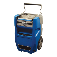
Quest PowerDry 1300:
Roto-mold design
8 Gallons per day at 80ºF/60%RH (AHAM)
5.0 amps of power
12-inch recessed wheels
Rotating handle
Solid state control panel
• Lightweight
Lighted cord
Condensate Pump
Water Removal Rate (Gallons/Day)
8 Gallons 80˚F, 60%
16 Gallons 90°F, 90%
quest
quest
Patent 8,938,981
Questions and Answers:

Quest Engineering PowerDry 1300 Specifications

General IconGeneral
BrandQuest Engineering
ModelPowerDry 1300
CategoryDehumidifier
LanguageEnglish

Summary

Safety Precautions

Safety Certifications

Ensures compliance with industry safety standards such as ANSI/UL 474 and CSA C22.2 No.92.

Specifications

Details key technical attributes including power, water removal capacity, blower CFM, and operating range.

Handle Installation

Step-by-step guide for correctly installing the unit's handle prior to first use.

Operation

Transporting

Guidelines for safely moving and transporting the dehumidifier, including vehicle placement.

Electrical Requirements

Specifies power connection needs, including circuit requirements and extension cord guidelines.

Condensate Removal

Explains the internal pump system for removing condensed water and manual purge function.

Ducting

Information on attaching lay-flat ducting to the unit's exhaust outlet.

Defrost Cycle

Describes the automatic defrost process triggered by frost formation on the evaporator coil.

Control Panel Functions

Details the operation of the POWER and PURGE buttons on the control board.

Hour Meter and Buttons

Explains the hour meter display and the function of the HOURS button for tracking usage.

Defrost Light Indicator

Indicates when the unit is in a defrost cycle and the compressor is off.

Maintenance and Storage

Air Filter Maintenance

Instructions for checking, cleaning, and replacing the unit's air filter for optimal performance.

Storage Procedures

Guidance on preparing the unit for storage to prevent water damage and biological growth.

Service and Troubleshooting

Technical Description

Explains the refrigeration system's operation, including compressor, condenser, and evaporator.

Troubleshooting Guide

Lists common operational issues and their potential causes and solutions.

Air Mover Service

Instructions for replacing the motorized impeller assembly.

Thermistor Replacement

Procedure for replacing the defrost thermistor, located on the refrigerant line.

Condensate Pump Service

Steps for replacing the internal condensate pump.

Float Safety Switch

Details the function of the safety switch that prevents overflow.

Parts and Warranty

Options & Accessories

Lists available optional accessories such as air filters and ducting.

Wiring Diagram

Schematic illustrating the electrical connections within the dehumidifier.

Service Parts List

Identifies replaceable parts with their corresponding part numbers.

Limited Warranty

Outlines the terms, coverage, and exclusions of the product warranty.

Related product manuals