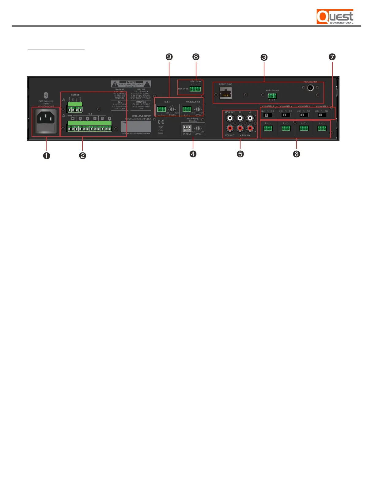
EasyManuals Logo

Quest Engineering PR-130BT User Manual

Quest Engineering PR-130BT
20 pages
To Next Page IconTo Next Page
To Previous Page IconTo Previous Page
Page #7 background imageLoading...
Page #7 background image
REAR PANEL
[Figure 1.2 Rear panel diagram]
1. AC 120 V 50/60Hz with fuse.
2. Speaker outputs connector ( individual zone and 100V, 4-ohm, 70V output ).
3. FM antenna, line output of media module and remote mic station (RM6) input jack.
4. Priority with Ducking Level Control & Channel Selector.
5. 2 Aux In, 1 Line Out & 1 Link Out.
6. 4 Balanced Mic/Line Inputs with 48V Phantom.
7. Line / Phantom / Mic selection switch for each input channel
8. Contact Closure to Rec/Play prerecorded messages.
9. Tel Paging and Music on Hold (M.O.H.) with volume controls
7 –
PR-130BT / PR-240BT

Questions and Answers:

Question and Answer IconNeed help?

Do you have a question about the Quest Engineering PR-130BT and is the answer not in the manual?

Quest Engineering PR-130BT Specifications

General IconGeneral
BrandQuest Engineering
ModelPR-130BT
CategoryAmplifier
LanguageEnglish

Related product manuals