28
EN
RETRACTABLE THRUSTER BTR185 - IT EN - REV008B
8/10 mm
INSTALLATION
Adjustment procedure
WARNING: the following procedure must be carried out by qualified personnel.
WARNING: presence of moving mechanical parts. Pay extreme attention when operating on the BTR propeller if connected
to power.
CAN2
UP DWN
POWER
LA STATUS
ERROR
LA
+
LA
-
LSC COM COM C
-
COMC
-
SXC
-
DXI
-
SXI
-
DXLSO
Fig. 18
B
A
D
C
Fig. 19
Fig. 17
RTC R1
PCB RTC R1
• Ensure that all electrical connections have been properly carried out.
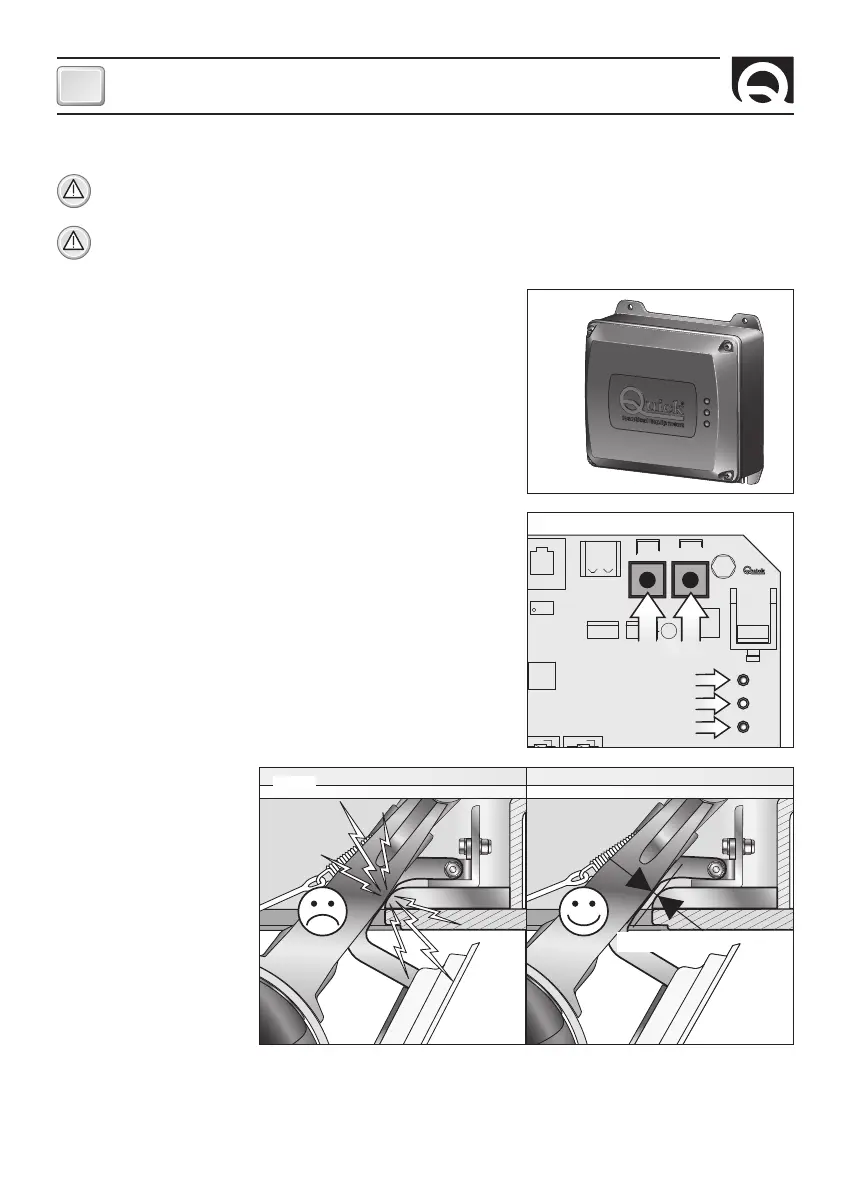
• Remove the cover from the card box (fig.17).
Limit switch adjustments must be made in “manual mode”.
• Holding down both buttons on the board (fig. 18 / part. A), connect power to
the RTC R1 electronic control board until the (green) POWER LED begins flash
-
ing rapidly (fig. 18 / part. B).
Then release both buttons.
• It is now possible to electrically control the actuator by means of the UP and
DOWN buttons.
• Press the DOWN button till the actuator can be hooked again to the lever (see
paragraph “System check and mechanic adjustment” fig. 15 A)
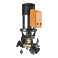
• By pressing the DOWN button, the thruster opens till the activation of the limit
switch and the STATUS LED becomes green.
If the limit switch isn’t in the correct position (fig. 19), it can be adjusted (see
paragraph Actuator’s adjustment).
• By pressing the UP button, it is now possible to check the closing of the lid;
once the limit switch is reached the STATUS LED becomes red: if this closing is
not enough, adjust the limit switch (see paragraph Actuator’s adjustment).
The thruster is already adjusted at the factory, so it shouldn’t need any
closing adjustment.
F