15
EN
RRC R02/12 - REV003A
INSTALLATION - OPERATION
COM
SHEILD
PROG
relè 4relè 3
NO2
NO1
NO4
NO3
V
+
V
-
relè 1 relè 2
ANT
1
COM
SHEILD
PROG
relè 1 relè 2
relè 3 relè 4
relè 5 relè 6
relè 8relè 7
relè 10relè 9
relè 12relè 11
NO1
NO3
NO5
NO2
NO4
NO6
NO8
NO10
NO12
NO7
NO9
NO11
V
+
V
-
ANT
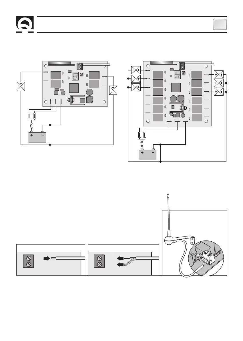
Start-up
The receiver starts-up once the power supply is connected. After start-up, the ON/OFF LED and all display seg-
ments will light up for a short time.
Awaiting signal status
The ON/OFF LED flashes slowly. The receiver waits for a valid command from a stored transmitter or for configura-
tion.
BATTERY
FUSE **
FUSE **
* DEVICES USED IN DIRECT CURRENT
** THE FUSE VALUE MUST BE CHOSEN BASED ON ABSORPTION
OF THE USED DEVICES.
*
*
*
*
COMMON FOR THE
USED DEVICES
COMMON FOR THE
USED DEVICES
10,5-31Vdc
10,5-31Vdc
BATTERY
1A QUICK ACTING F
1A QUICK ACTING F
FIG.2
OPERATION
R02 - R04 R06 - R08 - R10 - R12
EXTERNAL ANTENNA
If the installation of an external antenna is required, proceed as follows:
• remove the internal antenna, made of an 8 cm long folded wire, from the
ANT input (fig.3).
• Connect the centre core of the coaxial cable of the antenna to the ANT
input (fig.4). The metallic shield must be connected to the SHIELD input.
• Coaxial cable during laying must not be throttled and bended at a right
angle. Must also be taken away from heat sources.
• The antenna must be installed vertically at a distance of at least 1 metre
above the boat floating level, away from electrical sources of disturbance
and not inside any metal structures.
• Do not install the antenna close to that of other equipment as VHF, radar,
GPS, etc.
SHEILD
ANT
FIG.3
SHEILD
ANT
FIG.4
SHEILD
ANT
EXTERNAL ANTENNA
CONNECTION EXAMPLES
 Loading...