5 cm
5 cm
5 cm
5 cm
Riduttore di Tensione Switching
Switching Voltage Reducer
Abaisseur de Tension Switching
Switching Abspanner
Reductor de Voltaje Switching
VRS 10
10
I
8
t
V in +24 Vdc
V out +13,5 Vdc
GND
EQUIPMENT
12 V
BATTERY
24 V
10
OPERATING
GB
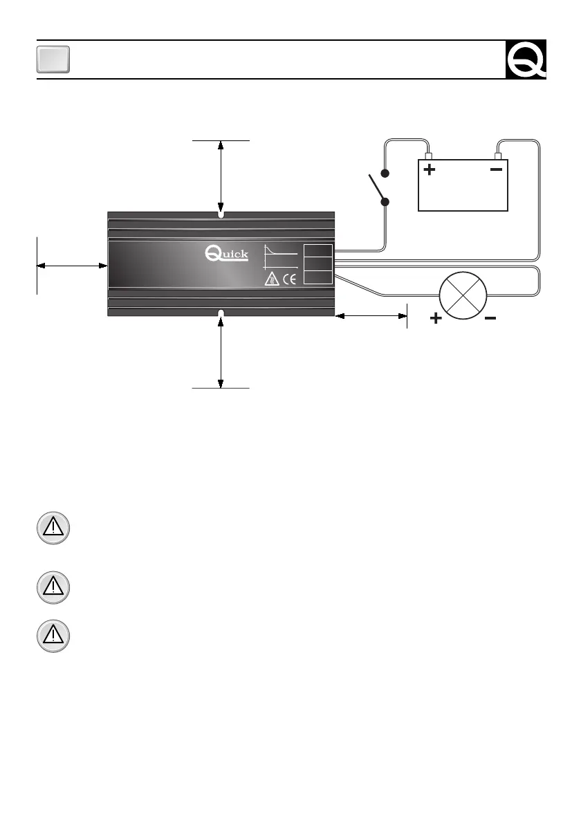
FIG. 1
ELECTRICAL WIRING
The equipment is to be wired up as shown in figure 1. Always check the input and output termi-
nals for correct polarity.
The electrical wiring is to be done in compliance with local electrical codes.
WARNING: before connecting the batteries, always check the battery cables for correct po-
larity. Remember that wrong polarity may seriously damage the voltage reducer even if the
protected by a fuse.
WARNING: before connecting or disconnecting the cables from the voltage limiter termi-
nals, make sure they are not live.
WARNING: the use of inadequate size cables and the incorrect connection of the terminals
or the electrical joints may result in dangerous overheating of the connecting terminals or
cables.