Do you have a question about the Quincy QOCS 25 and is the answer not in the manual?
Explains the meaning of various safety symbols used throughout the manual.
Outlines fundamental safety rules for installation, operation, and maintenance.
Details critical safety measures required during the installation phase.
Lists essential safety measures to follow during the equipment's operation.
Provides safety instructions for performing maintenance and repair tasks.
Covers safe procedures for dismantling and environmentally responsible disposal.
Introduces the Quincy condensate treatment devices and their functional purpose.
Explains the working principles of the QOCS condensate treatment units.
Presents physical dimensions, weights, and connection sizes for all models.
Provides detailed instructions for the correct installation of the unit.
Guides users through the initial setup and putting the unit into operation.
Outlines regular maintenance tasks and filter replacement for optimal performance.
Details available optional accessories for enhanced functionality.
Addresses the issue of a lot of oil entering the condensate treatment device.
Troubleshoots rising service indicators and excessive condensate flow.
Explains causes and solutions for cloudy condensate at the outlet, often due to sizing.
Defines the reference conditions and operational limitations for the device.
Provides detailed technical data including FAD values for different models and climates.
The Quincy Condensate Management system, encompassing models QOCS 25, QOCS 53, QOCS 106, QOCS 180, QOCS 360, QOCS 636, QOCS 1325, QOCS 2650, and QOCS 5300, is designed for the treatment of oil-containing condensate produced by oil-injected compressors. Its primary function is to separate oil from condensate and absorb it using filters, ensuring the treated condensate meets environmental requirements for disposal. The system is robust, being insensitive to shocks and vibrations, and compatible with all types of drains. The model designation number corresponds to the compressor's air capacity in litres per second.
Compressed air from oil-injected compressors contains a small amount of oil. When this air is cooled in the aftercooler and, if applicable, in a refrigeration dryer, oil-containing condensate forms. The QOCS units are condensate treatment devices that process this condensate.
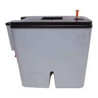
For QOCS 25 and QOCS 53 models, the condensate, containing fine oil droplets, enters the unit via an inlet and is depressurized through mufflers. It then flows to a first stage where it seeps through an oleophilic filter, which absorbs most of the oil. The water, still containing a small quantity of oil, then flows to a second stage with an organoclay filter, which absorbs almost all remaining oil. The clean condensate is then drained through the condensate outlet. These models are two-stage, replaceable units.
For QOCS 106 to QOCS 1325 models, the process is similar. Condensate enters via an inlet into mufflers for depressurization. It then flows to a first tower and seeps through an oleophilic filter (first stage) that absorbs most of the oil. The water, with residual oil, moves to a second stage where an organoclay filter (second stage) absorbs the remaining oil. The clean condensate is then drained. These models are two-stage, serviceable units. The oleophilic filter floats on the water, sinking deeper as it absorbs more oil. A service indicator moves downwards with the filter, signaling when replacement is due.
QOCS 2650 and QOCS 5300 models feature three stages. Condensate enters via inlets into mufflers for depressurization, then flows to a first tower with an oleophilic filter (first stage) that absorbs most oil. The water then moves to a second stage with an organoclay filter (second stage) for further oil absorption. Finally, it flows into a third stage with another organoclay filter (third stage) for final treatment. The clean condensate is then drained. These models are serviceable units. Similar to the QOCS 106-1325 series, the oleophilic filter's position and a service indicator signal replacement needs. The QOCS 5300 specifically consists of two identical units, requiring a flow divider to ensure equal condensate distribution.
The QOCS units are designed for an effective working pressure of 13 bar(e) (190 psig) and a compressor running time of 12 hours per day. They are compatible with various oil types including Organoclay, QuinSyn Plus, QuinSyn Endura, QuinSyn Edge, QuinSyn Prime, QuinSyn Flex, or any other synthetic oil, and are suitable for all types of oil-injected compressors.
Reference conditions for condensate treatment distinguish three climate types:
Operational limitations include:
The air capacity (FAD) of the compressor varies by model and climate:
For installations with compressors, air receivers, and filters, the FAD values are slightly higher. Correction factors are applied for operation exceeding 12 running hours per day, ranging from 1.00 for 12 hours to 0.5 for 24 hours. For poly-glycol based condensates, the capacity of each unit should be halved. To achieve an outlet oil carry-over of 5 mg/l instead of 10 mg/l, the compressor capacity (FAD) must be multiplied by 1/2.
Installation requires positioning the unit vertically on a level floor, with sufficient free space for filter replacement. The drain tube from the compressor to the separator should incline downwards to prevent condensate accumulation. Similarly, the outlet drain tube from the separator to the sewer must also incline downwards to prevent water pockets and flooding. Manual drains should be used with care to avoid exceeding the separator's depressurizing capacity. It is recommended to connect only one compressor, dryer, or filter per oil/water separator. For QOCS 5300, a flow divider must be installed at least 0.5 m above the units, ensuring it is level to distribute condensate equally.
Putting into operation involves removing the plastic bag from filters (without removing the net), ensuring the unit is not exposed to direct sunlight. For QOCS 106-1325, the lid and oleophilic filter are removed, the cartridge is secured, protecting plugs are removed, and the cartridge is re-secured. Mufflers are checked, clean water is poured into the unit until it exits the condensate outlet, the oleophilic filter is placed on the water surface (not pushed down), and the lid is replaced. QOCS 2650 follows a similar procedure, including connecting both cartridges with a flexible hose.
The product has an expected lifetime of 4000 hours. Filters should be checked regularly to prevent untreated condensate from entering the sewer, and condensate samples should be taken weekly. The turbidity of the outlet water should be checked weekly using the provided test capsule to indicate oil content. For exact oil content, a sample should be sent to a specialized lab.
Service kits are available for servicing, comprising genuine parts for components like oleophilic filters, organoclay filters, diffusers, and mufflers. The quantity of each component in a service kit varies by QOCS model.
Oleophilic filters should be replaced when the service indicator approaches the lid or when the test outlet condensate is less transparent than the reference test capsule. Filters should be replaced at least once per year, regardless of loading. Replacement involves stopping the compressor, depressurizing the system, removing the lid and oleophilic filter, cleaning the unit with water and tissue (avoiding soaps or detergents), removing and replacing mufflers and diffuser, and then proceeding with filter replacement instructions.
Filter replacement involves emptying the cartridge into a bucket, removing screws to detach it from the housing (QOCS 1325-5300 have wheels for easier removal), transferring the ball valve from the old to the new cartridge, and sealing the old cartridge with plugs. The new cartridge is then partially filled with clean water, pushed into the housing, secured, and the drained condensate is poured back in. Finally, the housing is filled with clean water until it flows out of the condensate outlet, and connections are inspected for leaks.
Optional features include electronic alarm sensors for condensate overflow and filter replacement, manifolds for connecting multiple condensate lines, wall-mounting brackets for QOCS 25-53, and spill containment kits to capture leaks.
| Brand | Quincy |
|---|---|
| Model | QOCS 25 |
| Category | Industrial Equipment |
| Language | English |