Do you have a question about the R.V.R. Electronica VJ3000 and is the answer not in the manual?
Guidance for treating extensive and less severe electrical burns, including immediate actions and medical attention.
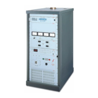
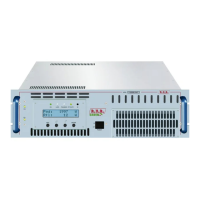
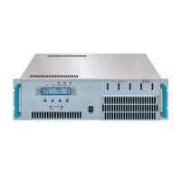
Details the physical characteristics of the VJ3000, including its rack cabinet, front panel, rear panel, and top flue.
Explains the VJ3000 as a grounded grid tube amplifier, its frequency range, power output, and design considerations.
Describes the front panel layout, including meters, tuning panel, alarm panel, and high voltage panel controls and indicators.
Refers to Table A for electrical and Table B for mechanical specifications of the VJ3000 unit.
Introduces the chapter detailing the operating theory of the VJ3000, subdivided into modules.
Describes the auxiliary power supply, including its components and configuration for both Threephase and Monophase versions.
Explains the protection card's inputs, trimmers, internal battery, and the operational logic for fault detection and unit disabling.
Details the optional single-phase voltage stabilizer, its components (variac, transformer, servo motor), and operation for voltage stability.
Describes the R.F. Chamber's three sections, motorized tuning mechanism, tube mounting, and temperature monitoring.
Identifies numbered components on the front and rear views of the VJ3000 unit as shown in Figure 1A.
Identifies numbered components on the top view of the VJ3000 unit as shown in Figure 1B.
Identifies numbered components in the total view of the VJ3000 unit as shown in Figure 2.
Details the function of each control and analog meter on the front meter panel for voltage, current, and power measurements.
Explains the press-buttons for input, load, anode, and grid tuning, and the switch for enabling tuning motors.
Details the functions of the reset switch, display, TIM/CICL button, and various alarm LEDs on the protection panel.
Describes the line power switch, ON/HV ON indicators, hour meter, and phase indicators on the high voltage panel.
Lists and identifies components within the Power Supply P1 unit for the three-phase version, including PROT-IN card, transformers, and resistors.
Lists and identifies components within the Power Supply P1 unit for the monophase version, including PROT-IN card, transformer, and resistors.
Identifies components of the Power Supply P2 unit for the three-phase version, including connector blocks, bridge rectifier, and discharge resistors.
Lists and identifies components of the Power Supply P2 unit for the monophase version, including connector blocks, bridge rectifier, and filter capacitors.
Identifies variable capacitors, tube socket, and inductance within the front view of the R.F. Cavity.
Identifies filament transformer, dividing transformer, cooling blower, and connectors on the rear view of the R.F. Cavity.
Identifies the Kapton capacitor (C18) on the right side view of the R.F. Cavity.
| Brand | R.V.R. Electronica |
|---|---|
| Model | VJ3000 |
| Category | Amplifier |
| Language | English |